
What Are the Components of Local Area Networks — Key LAN Elements Explained
Local Area Networks (LANs) Are Among the Most Stable Communication Mechanisms, Using Different Layers, such as data and physical, To Transmit Information.
In communications, networks that cover a limited area are called Local Area Networks (LANs), and networks that cover a wide area are called Wide Area Networks (WANs). LANs are generally divided into two main groups: wired and wireless.
Over the past two decades, various wired and wireless communication technologies have been introduced to the world of technology, and only a few have received attention.
The critical thing to note is that LANs will not be left out of the tech world. Unfortunately, some network experts have urged companies to use wireless LANs to reduce implementation costs, as these networks perform better than wired models.
The point to keep in mind is that wired LANs will not disappear, or at least not in the short term, because their stability, performance, and security are not comparable to those of wireless networks.
Therefore, it is better to check your business’s requirements before making a final decision and then choose the correct option.
Cable For Local Area Networks (Ethernet)
A local area network is a computer network designed for a limited geographic area, such as a building or campus. Although a LAN can be implemented as an isolated network to connect an organization’s computers and access shared resources, on a large scale today, most LANs connect to a WAN or the Internet.
In the 1980s and 1990s, various communication standards and protocols for wired LANs were developed, each with advantages and disadvantages. At the same time, the IEEE proposed that the data link layer be divided into Logical Link Control (LLC) sublayers and Medium Access Control (MAC) sublayers. Data (DLC) is called the Data Link Layer.
The institute developed several physical layer standards for various LAN protocols to simplify the management of local area networks and improve their performance. In general, all LAN wires use a media access control (MAC) mechanism that provides a secure way for network nodes to interact. Figure 1 shows how the IEEE 802 standard interacts with the TCP / IP protocol suite.
Ethernet was developed in the 1970s by Robert Metcalfe and David Boggs. Since then, four generations of this standard have been created: standard Ethernet (10 Mbps), fast Ethernet (100 Mbps), Gigabit Ethernet (1 Gbps), and 10 Gigabit Ethernet (10 Gbps).
Figure 2 shows the generation trend of different generations. Almost all innovative technologies for wired networks other than Ethernet have disappeared from the market, as Ethernet has been able to keep up with the changing world of technology.
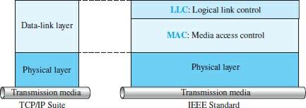
figure 1
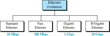
figure 2
Standard Ethernet (10 Mbps)
We call the introductory Ethernet data rates 10 Mbps. Standard Ethernet is the mother of all modern standards. Some features of this standard have changed or become obsolete, but some of the standard Ethernet features have not changed over the years and have been incorporated into other means. The unchanged features are as follows:
Offline and unreliable service
Ethernet provides offline service, meaning that each frame sent is independent of the previous or next frame. Ethernet does not define any mechanism for starting or ending a connection. The sender sends whenever he has a frame, in which case the receiver may be ready to receive or may not be.
This approach has a significant drawback, as the transmitter may send frames to the receiver consecutively, which reduces network performance. Here, if a structure is lost, the sender’s data link layer will not notice unless an upstream protocol (upper layer) monitors the sending process.
If a frame breaks during transmission and the receiver sees it, it will do nothing, as the upstream protocols must investigate and address the issue. So we have to say that Ethernet is not reliable by itself.
Frame Format
The Ethernet frame comprises seven fields designed to do a specific job (Figure 3). The description of each of these fields is as follows:
- Preamble: This 7-byte field is equivalent to 56 bits 0 and 1 alternately, notifying the receiving system of the next frame to be received to synchronize its time with the sender. This template sends only a warning and a time pulse. The 56-bit pattern allows stations to ignore some of the frames’ initial bits. Note that the Preamble field is added to the physical layer and is not formally part of the frame.
- Start Frame Delimiter: This field shows the one-byte (10101011) start of the frame. The SFD announces the last synchronization time to the station or stations. The last two bits are (11) and tell the recipient that the following field is the destination address. This field is the flag that marks the beginning of the frame and has a variable length. The SFD field is added to the packets at the physical layer.
- Destination Address: This 6-byte (48-bit) field holds the address of the link layer of the destination station or stations. The receiver extracts the data from the encapsulation and transfers it to the upper-layer protocol specified by this field.
- Source Address: This 6-byte field shows the packet sender link-layer address.
- Type: This field specifies the upper-layer protocol for encapsulating the package in the frame. Protocols include IP, ARP, OSPF, Open Shortest Path First, etc.
- Data: This field holds data encapsulated by upstream protocols that must be transmitted. The size of this field is at least 46 and at most 1500 bytes. The upstream protocol must have accurate information about the length of the data. If the data received from the upstream layer is more than 1500 bytes, the break process must be performed to allow the data to be placed in a frame. It must be filled with extra zeros if it is less than 46 bytes. This technique is called Padding. Here, data frames filled with extra zeros are passed to the upstream layer protocol, meaning that the upstream layer must remove or add extra zeros (Padding).
- CRC: The field contains error detection information called CRC-32. CRC handles the process of calculating addresses, types, and data fields. If the receiver computes the CRC value and finds that it is not zero, it realizes that a transmission failure has occurred and ignores receiving the frame.
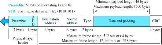
Figure 3
Frame size
Ethernet sets limits on the minimum and maximum size of a frame. For example, if the Ethernet network uses the CSMA / CD access method to send packets, a minimum length limit must be set to transmit packets smoothly. An Ethernet frame must be at least 64 bytes. Part of this site is related to the title and sequence.
If we count 18 bytes of the header and sequence (6 bytes of source address, 6 bytes of destination address, 2 bytes of length or type, and 4 bytes of CRC) and subtract the above value from 64, we get 46, which is the minimum length of the upstream layer. If the upstream layer package is less than 46 bytes, we must use the mentioned padding technique to compensate for the difference.
The Ethernet standard defines a maximum length of one frame (without preamble and SFD field) as 1518 bytes. If we subtract 18 bytes and reduce the sequence, the entire packet length is 1500.
Addressing
Each station on an Ethernet network (such as PCs, workstations, or printers) has its network interface card (NIC). The workstation network card specifies the address of the workstation link layer. This Ethernet address is 6 bytes written on a hexadecimal basis, and two dots separate its bytes. For example, an Ethernet URL could be written as follows:
47: 20: 1B: 2E: 08: EE
Transfer address bits
How to send addresses in the real world differs from how to write them in hexadecimal format. Here, the transition from left to right and byte is done. However, the least valuable bit (the rightmost bit) is sent first, and the last helpful bit is sent for each byte. A bit that defines an address as unicast or multicast is first delivered to the recipient.
The above approach helps the receiver determine if it receives a single-player or multi-player package. To clarify the discussion, pay attention to the following example. Figure 4 shows how the address 47: 20: 1B: 2E: 08: EE is sent.
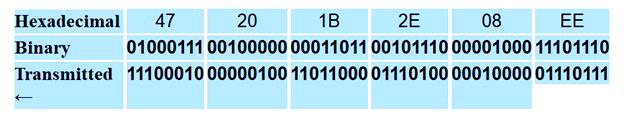
Figure 4
Unicast, Multicast, and Broadcast addresses
The source address is always unicast, meaning the frame only comes from one station. However, the destination address can be single-broadcast, multicast, or broadcast. If the low byte bit of the first byte in the destination address is 0, it is a single-bit address.
Otherwise, it is multicast. A multicast address is a particular type of multicast address that indicates the packet receivers of all LAN stations.
A destination broadcast address contains 48 1s (equivalent to F in a hexadecimal system). We must give a practical example to learn more about these three addresses. In the following example, we want to identify the following types of destination addresses:
4A: 30: 10: 21: 10: 1A
47: 20: 1B: 2E: 08: EE
FF: FF: FF: FF: FF: FFWe must look at the second hexadecimal digit from the left to identify the address type. The address is a single player if it is even (the least valuable bit is 0). If it is an individual (the least valuable bit is 1), it is a multicast address. And if all digits are F, the address is ubiquitous. So we have the following:
- The first is a single-address address because A is in the 1010 binary system (even).
- The second case is a multicast address because 7 in the binary system is 0111 (individual).
- The third case is an all-broadcast address because all digits on the hexadecimal basis F are equal to one.
Implementation
Standard Ethernet can be implemented in various ways, but only four are famous. The following table summarizes the implementation of standard Ethernet.
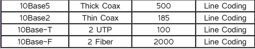
In the 10BaseX naming system, the number that replaces the X determines the data rate. Base means a digital (base) signal, and X indicates approximately the maximum cable size or type.
Standard Ethernet uses a baseband signal; the bits are converted to a digital signal and sent directly over the line.
Fast Ethernet (100 Mbps)
In the 1990s, some LAN technologies with a transfer rate of more than 10 Mbps emerged, such as Fiber Distributed Data Interface (FDDI) and Fiber Channel. Ethernet made a giant leap by increasing the transfer rate to 100 Mbps, so I used Fast Ethernet to describe it.
Of course, fast Ethernet designers had to adopt new technology compared to standard Ethernet; hence, the MAC sublayer remained unchanged.
This means the frame format and maximum and minimum sizes remain unchanged. As the transmission rate increased, standard Ethernet features that depended on transmission rate, access method, and implementation were revised. The goals of high-speed Ethernet can be summarized as follows:
- Upgrade data transfer speed to 100 Mbps.
- Standard Ethernet compatibility.
- Maintain the same 48-bit addresses.
- Maintain the same frame format.
Access method
Good CSMA / CD performance depends on transfer rate, minimum frame size, and maximum network length. If we want to keep the minimum frame size, the ultimate network length must change. In other words, if the minimum frame size is still 512 bits and packets are sent ten times faster, the collision should be detected ten times earlier, meaning that the maximum network length should be ten times shorter (propagation speed unchanged). Therefore, I developed two solutions for interaction with Fast Ethernet.
The first solution was to abandon the bus topology entirely and use a passive, star-shaped topology, increasing the maximum network size to 250 meters instead of 2,500 meters as standard Ethernet.
This approach was proposed for standard Ethernet compatibility.
The link-layer controller receives a frame from the source host and stores it in a buffer (queue) awaiting processing. The second solution is to use a buffer switch to store the shelves and connect the duplex to each host so that the transmission media has a private function for each host. CSMA / CD is not required in this case, as the hosts do not compete with each other to send packets.
It then checks the destination address and sends the frame from the appropriate interface. Since the connection to the switch is full-duplex, the destination address can even send a frame to another station simultaneously with receiving it.
Auto-negotiation
The above part offers a wide range of station or hub features. A new feature added to Fast Ethernet is called Auto-negotiation. Automated negotiation allows two devices to negotiate data mode or rates. The above approach is specifically designed to enable incompatible devices to connect. For example, a device with a maximum data rate of 10 Mbps can communicate with a device with a data rate of 100 Mbps (it can operate at a slower speed).
Topology
Fast Ethernet is designed to connect two or more stations. If there are only two stations, they can be connected point by point. Three or more stations should be combined in a star topology with a hub or switch in the center (Figure 5).
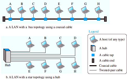
Figure 5
Encoding
Fast Ethernet uses a Manchester encoding scheme with a 200 Mbaud bandwidth. This makes the technology unsuitable for media such as tangled cables, designers looking for an alternative coding/decoding scheme.
However, no plan worked equally well for all three implementations. Therefore, three good coding schemes, 100Base-TX, 100Base-FX, and 100Base-T4, were proposed.
Gigabit Ethernet (1000 Mbps)
The need for faster data transfer led to the emergence of the Gigabit Ethernet standard (1000 Mbps). Gigabit Ethernet aimed to speed up data transfer up to 1 Gbps, keeping the address length, frame format, and maximum and minimum frame lengths constant. The bar is also compatible with the 802.3z standard.
The most important goals of Gigabit Ethernet are:
- Upgrade data transfer speed to 1 Gbps.
- Standard or fast Ethernet compatibility.
- Maintain the same 48-bit addresses.
- Maintain the same frame format.
- َAnd maintain minimum and maximum frame length.
- Support for auto-negotiation is just as fast as Ethernet supports it.
In recent years, Ethernet has played an essential role in metropolitan areas’ infrastructure. The IEEE Committee registered 10 Gigabit Ethernet as a standard 802.3ae. The design goals of 10 Gigabit Ethernet can be summarized as upgrading the data transfer rate to 10 Gbps, which increases data transfer speed and distance covered.
Other goals of this project included maintaining the same frame size and format, and the possibility of connecting LAN, MAN, and WAN networks. The standard defines two types of physical layers: LAN PHY and WAN PHY. The first standard (LAN PHY) supports shared local area networks, and the second describes a WAN with connections via SONET OC-192.
MAC sublayer
One of the primary considerations in the evolution of Ethernet was the preservation of the Mac sublayer. However, it was impossible to maintain this architecture to achieve data speeds of 1 Gbps. Gigabit Ethernet uses two semi-duplex and all-duplex techniques to transmit data. Almost all Gigabit Ethernet implementations follow the all-duplex approach, so the semi-duplex mode is rarely used.
A central switch is connected to all computers or switches in full-duplex mode.
In this case, each switch has buffers that hold data until it is sent to each input port. Since the controller uses the frame’s destination address and does not send the rack outside the port connected to that particular destination, there is no collision.
In other words, the CSMA / CD access method is no longer used. Gigabit Ethernet can also be used in semi-duplex mode, although it is not common.
In this case, a switch can be replaced with a hub that acts as a standard cable, which can lead to a collision. The semi-duplex approach uses the CSMA / CD access method.
FAQ
What are the main hardware components of a LAN?
Typical LAN hardware includes devices (computers, servers, printers), network interface cards (NICs), switches, routers, Ethernet cables, and wireless access points for Wi‑Fi connectivity.
What role does a switch play in a LAN?
A switch connects multiple devices within the LAN and forwards data only to the intended recipient using MAC addresses, improving efficiency and reducing unnecessary traffic.
Why are network interface cards (NICs) necessary?
NICs enable each device to connect to the LAN by providing the hardware interface for wired or wireless communication on the network.