


If You’re A Network Expert, Take The Data Link Layer Seriously – Applied Layers Of Strategic Importance
Typically, Professionals Who Enter The World Of Networks And Jobs Related To Networks And Infrastructure Have Basic Knowledge In This Field; however, One Of The Problems.
Network infrastructure. To be more precise, some people are skilled in managing and configuring firewalls for Sophos, Fortigate, Horizon, and Vampire virtualization, Splank products, and the like. Still, when faced with an underlying network problem, they must spend time finding the cause of the error. One of the reasons for this is the lack of mastery of the underlying concepts of the network world, especially the Datalink Layer.
The layer plays a crucial role in connecting the equipment of a LAN and the Internet, and in this article, we want to get acquainted with its various features.
One of the most important reasons we think about improving our knowledge about the link layer is security.
Hackers seldom directly attack a country’s communications infrastructure and, in most cases, try to make subtle changes to packets and bits of information. In this case, no security tool can detect these changes, but in practice, the sender achieves the desired goals by making minor changes to the packets in the data link layer.
The Internet is a collection of networks that hosts various components such as routers, switches, servers, workstations, etc. If a packet is transmitted from one host to another, it must pass through these networks to reach its destination. Figure 1 shows the relationship between Alice and Bob.
This figure clearly shows what devices, networks, and Internet service providers must pass through when you want to send the packet to reach your destination. Regardless of the various devices installed within these networks, the data link layer is responsible for communicating. Therefore, any problem in this layer prevents the correct sending or receiving of information.
In Figure 1, the data link layer on Alice’s computer withThe data link layer communicates with the R2 router. The data link layer on the R2 router communicates with the data link layer on the R4 router. This process continues until, finally, the data link layer on the R7 router communicates with the data link layer on the Bob computer.
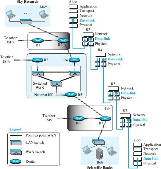
figure 1
Nodes and links
Although communication at the application, transmission, and network layers is global, or more precisely, end-to-end, communication at the data link layer is node-to-node. When a packet is sent from a point on the Internet, it must pass through various local and wide area networks to reach its destination. Routers connect these LANs and WANs.
The two end hosts and routers, nodes, and networks are called connections. Although two nodes are physically connected by a transmission medium such as a cable or radio waves, we must remember that the data link layer controls how the media is used. We can link a data layer have to use the total capacity of the media. Also, we can have a data link layer that uses only part of the link capacity.
Finally, we can have a point-to-point link or a broadcast link.
Then in a dot-to-dot connection, the link is assigned to two devices.
And in a broadcast link, a link is shared between several pairs of devices. For example, when two friends use the Internet at home to chat, they use a point-to-point connection. When the same two friends use their cell phones, they use a broadcast link based on radio waves.
Two sub-layers
To better understand the functionality and services provided by the data link layer, it can be divided into two sublayers: Data-Link Control (DLC) and Media Access Control (MAC). Interestingly, LAN protocols use the same strategic policy.
The Data Link Control (DLC) sublayer is responsible for handling all issues related to point-to-point links and broadcast links, while the MAC sublayer only deals with specific link issues; In other words, as you can see in Figure 2, we separate these two types of technology in the link layer.
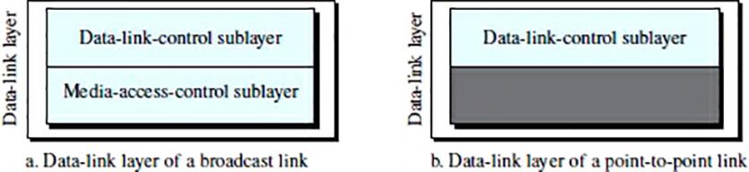
figure 2
Datalink control
Connected control ( DLC) establishes communication between two adjacent nodes (node-to-node communication) through specific policies and procedures. To be more precise, for data link control, it does not matter if the link is proprietary or comprehensive. This component has a linked layer responsible for configuring and controlling errors.
Framing
Data transfer in the physical layer means the transfer of bits as a signal from the source to the destination. The physical layer manages the sync bits to ensure they use the exact timing and bit.
On the other hand, the data link layer must wrap the bits in the frames; So that each frame is distinguishable from the other. The function of this layer is similar to sending an official letter. You insert a note in the envelope and deliver the letter to the post office. Each letter has its information in the post office, which is different from other letter information.
Here, the envelope acts as a separator. In addition, each envelope has a specific sender and recipient address that helps the postal company deliver the letter to the correct destination. If the recipient does not receive the letter, the sender will be able to track the non-sending. The same rule applies in the world of networks.
Framing in the data link layer, Distinguishes information that represents the sender’s address and the destination address. The sender’s address helps the recipient to know who sent the package. The destination address specifies where the box is going.
Although the whole message can package in one frame, this is not usually the case. One reason is that a structure can be too large, making the process of flow control and error detection inefficient. When a message is split into smaller frames, a unique error affects that small frame. When a message is transmitted in a massive structure, even a one-time error causes you to have to send a frame twice.
Frame size
Frames can be fixed or variable in size. There is no need to define the frame boundaries in fixed-size framing, as the site is used as a separator. An example of this is the ATM WAN configuration, which uses fixed-size frames called cells.
In variable size framing, we need a method to define the end of one frame and the beginning of the next. Therefore, the rough size framing is typical in local area networks and is very important. Two techniques are available here: Bit-Oriented and Character-Oriented.
Character-oriented framing
In character-oriented (or byte-oriented) configuration, the data to be transmitted are 8-bit characters based on an ASCII encoding system. In this mechanism, the header usually dispatches the source, destination, and other control addresses, and the trailer transmits additional error detection bits multiples of 8 bits. An 8-bit (1-byte) flag is added at the beginning and end of a frame to separate one frame from the next.
A flag with unique characters associated with a protocol indicates the beginning or end. Figure 3 shows the format of a frame in a character-oriented protocol.
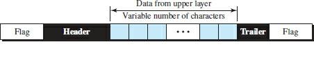
Figure 3
Character-oriented framing was widely used when data layers bound information transmitted in text mode. Here we could choose the flag as any character that is not used for text communication, but now that we are sending other types of information, such as diagrams, audio, and images, any pattern used for the flag can be part of the information. If this happens, the client’s protocols, when they receive such a pattern, assume they have reached the end of a connection, and the connection is terminated abruptly.
The byte stuffing strategy adds to the character-oriented framing approach to solve this problem. In the byte filling mechanism, when a character with the same flag pattern exists, a specific byte is added to the data part of the frame.
This byte is commonly called an escape character (ESC) and has a predefined bit pattern.
When the receiver encounters the ESC character, it removes it from the data section and treats the next character as data, not as a flag. However, the Byte Stuffing technique, which added the escape character to the flag in the data frame section, caused another problem. What happens if the text contains one or more escape characters with a byte with the same pattern as the flag? The receiver deletes the escape character but retains the next byte, which is mistakenly interpreted as the end of the frame.
In this case, a persistent connection problem arises. The escape characters part of the text must be distinct from the escape characters to solve this problem. In other words, if the escape character is part of the text, a double character must add to indicate that the second character is part of the text. Figure 4 shows this situation.
However, the Byte Stuffing technique, which added the escape character to the flag in the data frame section, caused another problem. What happens if the text contains one or more escape characters with a byte with the same pattern as the flag? The receiver deletes the escape character but retains the next byte, which is mistakenly interpreted as the end of the frame. In this case, a persistent connection problem arises.
The escape characters part of the text must be distinct from the escape characters to solve this problem.
In other words, if the escape character is part of the text, a double character must add to indicate that the second character is part of the text. Figure 4 shows this situation. However, the Byte Stuffing technique, which added the escape character to the flag in the data frame section, caused another problem. What happens if the text contains one or more escape characters with a byte with the same pattern as the flag? The receiver deletes the escape character but retains the next byte, which is mistakenly interpreted as the end of the frame.
In this case, a persistent connection problem arises. The escape characters part of the text must be distinct from the escape characters to solve this problem. In other words, if the escape character is part of the text, a double character must add to indicate that the second character is part of the text.
Figure 4 shows this situation. What happens if the text contains one or more escape characters with a byte with the same pattern as the flag? The receiver deletes the escape character but retains the next byte, which is mistakenly interpreted as the end of the frame.
In this case, a persistent connection problem arises.
The escape characters part of the text must be distinct from the escape characters to solve this problem.
What happens if the text contains one or more escape characters with a byte with the same pattern as the flag? In other words, if the escape character is part of the text, a double character must add to indicate that the second character is part of the text. Figure 4 shows this situation. The receiver deletes the escape character but retains the next byte, which is mistakenly interpreted as the end of the frame.
In this case, a persistent connection problem arises. The escape characters part of the text must be distinct from the escape characters to solve this problem. In other words, if the escape character is part of the text, a double character must add to indicate that the second character is part of the text. Figure 4 shows this situation.
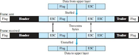
Figure 4
Character-oriented protocols create another problem in data communication. The global encoding systems used today, such as Unicode, have 16-bit and 32-bit characters that contrast with 8-bit characters. Because of such problems, companies turned to bitcoin protocols.
Bitwise framing
In bituminous framing, the data portion of a frame is a sequence of bits interpreted by the top layer as text, graphics, audio, video, etc. However, in addition to the headers (and possible arrangements), we still need a delimiter to separate one frame from another. As Figure 5 shows, most protocols use a special 8-bit pattern flag, 01111110, as the frame’s beginning and end definition separator.
However, this flag can cause the same problem that we saw in the character-oriented protocol, which means that if the flag pattern appears in the data, we must inform the recipient that this is not the end of the frame. We do this by filling in a bit (instead of a byte) so that we do not have a flag-like pattern. If we have one bit 0 and five consecutive 1 bits in the bit approach, a double 0 is added to the packet. This strategy is called Bit Stuffing.
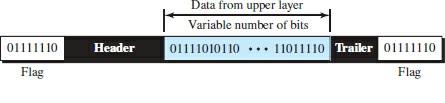
Figure 5
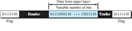
Figure 6
Error control
Error control refers to error detection and retransmission methods in the data link layer. The error control performs both error detection and correction processes. The above approach allows the receiver to notify the sender of missing or damaged frames during transmission and coordinates the retransmission of those frames by the sender.
Types of errors
When bits are moved from one point to another, they are subject to unpredictable changes that ultimately change the nature and shape of the signal. The one-bit error means that only 1 bit of a given data unit (such as a byte, character, or packet) changes from 1 to 0 or 0 to 1.
An essential term is called “explosive error,” which means that two or more bits in a data unit have changed from 1 to 0 or 0 to 1. Figure 7 shows the effect of one-dimensional error and an explosive error on a single data unit, respectively.
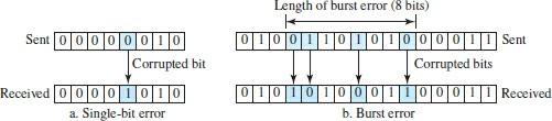
Figure 7
The explosive error occurs more often than a single-bit error because the duration of the noise signal is longer than the duration of one bit; That is, when noise affects data, it involves a set of bits. The number of bits affected depends on the speed of the transmission media and the duration of the noise. For example, if we send data at a rate of 1 kbps, the noise of 1/100 of a second can affect 10 bits. If we send data at a speed of 1 Mbps, the same noise can affect 10,000 bits.
Redundancy
An important factor that facilitates detecting or correcting errors is redundancy. To identify or correct mistakes, we need to send a few extra bits along with the data. These extra bits are added by the sender and removed by the receiver. Their presence allows the receiver to identify or correct broken bits.
Diagnosis versus correction
Errors are more challenging to correct than to detect. We only seek to examine whether an error has occurred in error detection. The answer to a yes or no is simple, and we do not even care about the number of broken bits.
In error correction, we need to know the exact number of broken bits and, more importantly, their location in the message. The number of errors and the size of the message is other essential factors that we must consider. If we want to correct a mistake in an 8-bit data unit, we must consider eight possible error locations. Imagine the receiver’s big problem finding ten errors in a 1000-bit data unit.
coding
Redundancy is achieved through various coding schemes. The transmitter adds extra bits through a process that creates a connection between the extra bits and the actual data bits. The receiver examines the relationships between the two-bit sets to detect errors.
The ratio of extra bits to data bits and process coherence are essential factors in any coding scheme. We can divide coding schemes into two general groups: block coding and convolution coding, which are beyond the scope of this article.
last word
We can consider the data link layer as two sub-layers. The top layer is responsible for link control, and the bottom layer is responsible for media access. Here, data link control (DLC) is concerned with the design and procedures that make communication between the two nodes possible.
This sublayer is responsible for framing and error control. As you can see, error control is directly related to data corruption during transmission; therefore, as a network expert, it is essential that you upgrade your knowledge of link layer protocols, in particular the two protocols HDLC and PPP.
Datalink control high-level Data Link Control (HDLC) High-level Data Link Control is a bitcoin-based protocol for communicating through point-to-point and multi-point links. However, the most common protocol for two-node access is the point-to-point (PPP) protocol, a byte-oriented protocol.
Today, various protocols for access management and communication have emerged that can be divided into random access protocols, controlled access protocols, and channeling protocols. One station is not superior to another in random access methods, and no control is given to anyone.
In controlled access, stations interact to determine which station has the right to send. Channelization is a multiple access method in which the available bandwidth of a link is shared between different stations.
In the data link layer, We use link-layer addressing. The system usually finds the address of the next node-link layer using the ARP protocol called Address Resolution Protocol.
As you can see, this layer is essential in the network world and should not be overlooked. In this article, we tried to show general information about the function of this layer. Still, if you are looking for complete details, you should go to the primary language resources.