How To Configure Cisco Catalytic Switches? Set The IP Address On The Switches
There is a lot of variety when it comes to enabling the configuration of Cisco Catalytic Switches. Some Operate At 10 Mbps, Others at 10 Gbps, and Others Use A Combination Of Fiber-Optic And Ethernet Ports To Deliver The Highest Throughput.
Advanced switches, such as the Model 3850, use intelligent capabilities to send data quickly. In this article, we will learn how to configure Cisco catalytic converters.
The switches are configured using the command-line interface (CLI). Typically, network experts configure switches in two ways. First group: Some configure the initial settings to make the button work smoothly, while others go to advanced settings, including VLAN configuration, Inter-Switch Link (ISL), and 802.1q trunking.
Here are some basic things to look for when selecting yours:
- Configure management settings.
- Configure IP address and subnet mask.
- Set the default IP gateway.
- Set the Port Security feature.
- Network testing and verification.
Cisco Catalytic Switches configuration
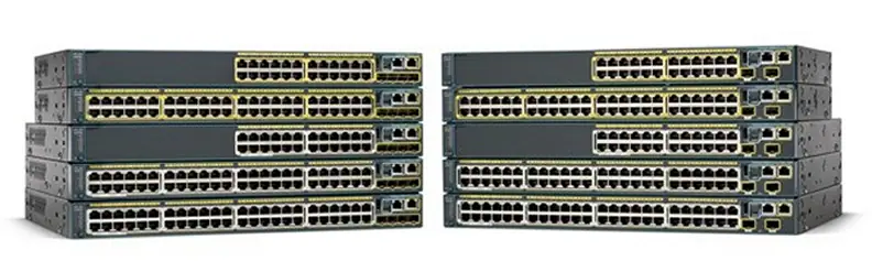
Before configuring Catalyst switches, you should know how to boot them. Figure 1 shows a typical Cisco catalyst switch.

The first thing to note is that the console port for the catalytic converter switches is on the back of the device. On switches like the 3560 shown in Figure 1, the console is directly in front of the device to make it easier to use. The 2960 eight-port switches are similar to the 3560.
If the POST operation is completed successfully, the LED on the device will turn green, but the POST operation will have a problem; the amber light will indicate a severe problem. The bottom button on the left panel of the device shows which ports are using Ethernet (PoE).
To do this, you must press the Mode button.
As you know, PoE is a helpful feature that allows you to use the same cable for power and data transmission without additional cabling. Figure 3 shows the networks in which the switch is configured, and we intend to describe its operation.
You can use any Layer 2 switch on a standard network, but when it comes to complex networks, you should use at least one router plus a Layer 3 switch like the 3560. If you have more than one switch on the web, you need to connect them via a crossover.
The 3560 buttons can detect the connection type automatically, so you can also use direct cables (Straight), but note that not all switches can automatically detect the cable type.
Different switches have different needs and capabilities, so keep this in mind when connecting separate switches.
When you first connect the switch ports, the link lights are amber and turn green after a few seconds, indicating that the button has no hardware problems. Connecting to a switch port that turns green and amber alternately means the port has encountered an error.
When this happens, check the docks’ host network card, cabling, and two-way settings to ensure they match the host settings.
Do we need to set the IP address on the switches?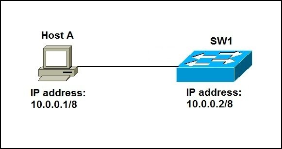
In general, switches are equipped with active standby ports. When you take the control out of the box, it connects the clients to the power and then switches to the router. The controller then starts learning the MAC addresses. However, the button must have an IP address to be managed more efficiently.
Protocols such as Telnet, SSH, SNMP, etc., all require an IP address to communicate with a switch within a local area network. Remember, since all ports are enabled by default, you must close unused ports or assign them to a new VLAN for security reasons.
According to our explanation, how should we assign this management IP address to the switch? The best place is the VLAN management interface, a routing interface on Cisco switches called VLAN 1.
This management interface can change, and Cisco recommends that you change it to improve security. Now, let’s configure the controls shown in Figure 3.
Switch S1
We start by connecting to each switch and setting up management functions. We also assign an IP address to each button, but this is not done to improve network performance; it is only because of the switch’s remote management capability. Let’s use a simple IP design like 192.168.10.161/28. The commands we run to configure the controller are shown in Figure 4.
Switch>en
Switch#config t
Switch(config)#hostname S1
S1(config)#enable secret todd
S1(config)#int f0/15
S1(config-if)#description 1st connection to S3
S1(config-if)#int f0/16
S1(config-if)#description 2nd connection to S3
S1(config-if)#int f0/17
S1(config-if)#description 1st connection to S2
S1(config-if)#int f0/18
S1(config-if)#description 2nd connection to S2
S1(config-if)#int f0/8
S1(config-if)#desc Connection to IVR
S1(config-if)#line con 0
S1(config-line)#password console
S1(config-line)#login
S1(config-line)#line vty 0 15
S1(config-line)#password telnet
S1(config-line)#login
S1(config-line)#int vlan 1
S1(config-if)#ip address 192.168.10.17 255.255.255.240
S1(config-if)#no shut
S1(config-if)#exit
S1(config)#banner motd #this is my S1 switch#
S1(config)#exit
S1#copy run start
Destination filename [startup-config]? [enter]
Building configuration…
[OK]
S1#
The first thing to note is that no IP address is configured on the switch’s physical interface. The configuration process is simple since all ports on a switch are enabled by default.
The IP address is configured under a logical interface called a management domain, or VLAN. You can use the default VLAN 1 to manage a switched network, as we did, although you can also use another VLAN.
There are no IP addresses in physical switch relationships, routing protocols, etc. We are focusing on Layer 2 switching, not routing. Also, note that Cisco switches do not have an AUX port.
S2 switch
The S2 switch configuration is as follows:
Switch#config t
Switch(config)#hostname S2
S2(config)#enable secret todd
S2(config)#int f0/1
S2(config-if)#desc 1st connection to S1
S2(config-if)#int f0/2
S2(config-if)#desc 2nd connection to s1
S2(config-if)#int f0/5
S2(config-if)#desc 1st connection to S3
S2(config-if)#int f0/6
S2(config-if)#desc 2nd connection to s3
S2(config-if)#line con 0
S2(config-line)#password console
S2(config-line)#login
S2(config-line)#line vty 0 15
S2(config-line)#password telnet
S2(config-line)#login
S2(config-line)#int vlan 1
S2(config-if)#ip address 192.168.10.18 255.255.255.240
S2(config)#exit
S2#copy run start
Destination filename [startup-config]?[enter]
Building configuration…
[OK]
S2#
We should now be able to ping to switches S1 and S2
S2#ping 192.168.10.17
Type escape sequence to abort.
Sending 5, 100-byte ICMP Echos to 192.168.10.17 timeout is 2 seconds:
.!!!!
Success rate is 80 percent (4/5), round-trip min/avg/max = 1/1/1 ms
S2#
Well, why did I take only four pings instead of five? The first time [.] It is a timeout, but the exclamation mark [!] Means the operation was successful. The first ping did not work because ARP spent time converting the IP address to the corresponding hardware MAC address.
S3 switch
The configuration of the third switch is as follows:
Switch>en
Switch#config t
SW-3(config)#hostname S3
S3(config)#enable secret todd
S3(config)#int f0/1
S3(config-if)#desc 1st connection to S1
S3(config-if)#int f0/2
S3(config-if)#desc 2nd connection to S1
S3(config-if)#int f0/5
S3(config-if)#desc 1st connection to S2
S3(config-if)#int f0/6
S3(config-if)#desc 2nd connection to S2
S3(config-if)#line con 0
S3(config-line)#password console
S3(config-line)#login
S3(config-line)#line vty 0 15
S3(config-line)#password telnet
S3(config-line)#login
S3(config-line)#int vlan 1
S3(config-if)#ip address 192.168.10.19 255.255.255.240
S3(config-if)#no shut
S3(config-if)#banner motd #This is the S3 switch#
S3(config)#exit
S3#copy run start
Destination filename [startup-config]?[enter]
Building configuration…
[OK]
S3 #
Now, let’s ping switches S1 and S2 via switch S3. In this case, we will see the following outputs:
S3#ping 192.168.10.17
Type escape sequence to abort.
Sending 5, 100-byte ICMP Echos to 192.168.10.17, timeout is 2 seconds:
.!!!!
Success rate is 80 percent (4/5), round-trip min/avg/max = 1/3/9 ms
S3#ping 192.168.10.18
Type escape sequence to abort.
Sending 5, 100-byte ICMP Echos to 192.168.10.18, timeout is 2 seconds:
.!!!!
Success rate is 80 percent (4/5), round-trip min/avg/max = 1/3/9 ms
S3#sh ip arp
Protocol Address Age (min) Hardware Addr Type Interface
Internet 192.168.10.17 0 001c.575e.c8c0 ARPA Vlan1
Internet 192.168.10.18 0 b414.89d9.18c0 ARPA Vlan1
Internet 192.168.10.19 – ecc8.8202.82c0 ARPA Vlan1
S3 #
At the output of the show IP arp command, a dash (-) in the minute column means that the interface is a physical device.
Now, before we look at the switch settings, there is another command you need to know about it. It is the IP default gateway command. If you want to manage your switches from outside your local network, you need to set a default gateway on the switches just like a host and do so from a global configuration.
Here is an example where we introduce our router with an IP address using the last IP address in our subnet area:
S3#config t
S3(config)#ip default-gateway 192.168.10.30
As you can see, the three switches are configured according to the pattern in the figure above. To protect your buttons more efficiently, you can do more advanced things, such as port security.