Differences Between VLAN and Subnet in Computer Networks
As networks grew larger, this architecture became unusable and faced numerous problems due to its unicast nature.
For this reason, practical technologies such as virtual local area networks (VLANs) and subnets emerged, which are the most critical components of TCP/IP networks.
These technologies are widely used to segment large networks, making them more manageable and efficient. However, some web and IT professionals still do not know the difference between these concepts.
Overview of VLAN and Subnet
Virtual LANs operate at layer 2 of the OSI model and use different broadcast domains to separate local network traffic. Hosts on the same VLAN can communicate without issues, but hosts on other VLANs cannot communicate by default unless Layer 3 routing is configured between them.
Subnetworks in layer 3 of the OSI model are used to build small layer-3 networks based on the IP address of a larger network. The diagram of a simple network is shown in Figure 1. Let’s explore the differences between VLANs and Subnets in more detail.
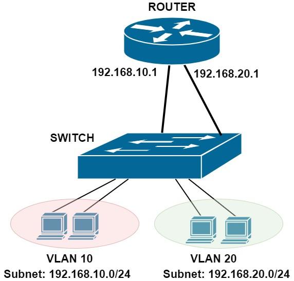
Figure 1
In Figure 1, you see a network with two virtual LANs (10 and 20) and two subnets with addresses (192.168.10.0/24 and 192.168.20.0/24). Although hosts in two virtual LANs are connected to the same switch, they cannot communicate with each other over the switch.
If hosts in VLAN 10 want to communicate with hosts in VLAN 20, traffic from hosts in VLAN 10 must be forwarded to the router interface with IP address 192.168.10.1, which then forwards packets to its second interface (192.168.20.1). Slow to reach VLAN 20, finally.
What is a VLAN?
Virtual Local Area Networks (VLANs) isolate Ethernet traffic on a local area network at layer 2 (data link layer) of the OSI model. Without VLANs, every packet transmitted over the network can be received by all devices, and devices can communicate with each other.
From a security point of view, such a situation is not ideal because, in a corporate environment, users based in the filing unit are not supposed to have access to the information of the financial department, or in an academic setting, students are not supposed to have access to the knowledge of the IT unit.
To solve this problem, we should use traffic isolation by defining and implementing VLANs on the switch interfaces to which endpoint devices are connected. The controller tags the packets with a VLAN ID number when traffic is sent from these endpoint devices to the switch. It is called 802.1Q VLAN tagging.
When a packet arrives at a switch port (access port on Cisco devices), the switch assigns an 802.1Q tag (VLAN ID) to the Ethernet frame. Now the switch forwards this frame only to other ports that belong to the same VLAN.
If the label matches the VLAN assigned to the interface, the packet is allowed; otherwise, it is dropped. This process is just like the lanes of a highway.
These separate lines represent different VLANs.
Another practical example in this field is a building with four doors in red, green, yellow, and blue colors that lead to 4 different rooms. From a group of 40 people, 10 may pass through the red door, 10 through the green door, 10 through the yellow door, and 10 through the blue door.
If a person with a red permit attempts to enter through the blue door, the card reader will display an error message, preventing them from opening the door and entering the room, unlike people with a permit to open the blue door. In this case, he can only enter the room where the color is red.
Now we come to the critical question: what happens if a VLAN-tagged interface receives a packet without a VLAN tag? By default, this packet is removed; we use a technique called Native VLAN to keep it. The native VLAN handles all untagged packets and is VLAN 1 by default on Cisco switches. The VLAN tagging process is precisely based on this rule.
Professional experts often adjust this value to prevent potential issues with the default number of local virtual networks. On a trunk interface, all VLAN-tagged traffic is allowed only for a specific link or VLANs.
Also, untagged network traffic will be assigned a Native VLAN tag and then routed through the trunk. Accordingly, both sides of the native VLAN communication mechanism must be in the same compartment, because if they use different native VLANs, the switch will drop untagged traffic due to a mismatch.
What is a Subnet?
Many IP addresses are lost in such a situation, even in large networks. A technology called a subnet has been developed to solve this problem. A subnet is a small Layer 3 IP network created by dividing a larger network into smaller segments within its IP address range. A class, A IP address with a subnet mask of 255.0.0.0, allows defining 127 networks with 16,777,216 IP host addresses per network.
A class A IP address can be divided into smaller segments. These smaller segments are networks defined and usable in the same range as the primary IP address. The IP address 10.0.0.1 with a netmask of 255.255.255.0 (/24) represents about 2 million subnets, but only 254 usable IP addresses per subnet. The subnet mask is changed from/ from/8 (255.0.0.0) to a smaller mask with fewer IP addresses.
By dividing an extensive IP address range into smaller subnets, management becomes more precise, and the IP address space is used more efficiently.
In switch-based networks, each subnet is associated with its VLAN. As you saw in network diagram one, there is a direct mapping between VLANs and Subnets. In large organizations, network administrators partition their LANs into multiple virtual LANs, each with its own Layer 3 subnet.
If we want to use an analogy in this context, we should say that layer-3 subnets are like rooms in an organization. People in the same room can communicate freely. However, if you want to go to another room (subnet), you must use a door (router gateway) that leads to other sections.
Comparison of VLAN and Subnet
Subnets are used to separate network traffic more precisely. Still, the main difference between VLANs and subnets is that VLANs use a Layer 2 mechanism to separate Ethernet traffic within the switching infrastructure. In contrast, Subnets use a Layer 3 mechanism to separate traffic. They state that the above process is done in the routing infrastructure.
In the real world, VLANs and Subnets are used in infrastructure to enhance security by providing a unified defense against security threats, as both methods can segregate internal network traffic. Although VLANs can separate traffic, communication still occurs only at layer 3.
However, there are situations where you may want different VLANs to communicate with each other. For example, you have a file server connected to a switch configured for Vlan 10, and a PC connected to the same switch but configured for Vlan 20 should be able to communicate with the file server.
In this case, the two components in layer two cannot communicate because they are in different VLANs.
For a networked device, such as a desktop computer, to communicate with a server, a Layer 3 router must perform inter-VLAN routing. As shown in Figure 1. Another way to implement Inter-VLAN routing is to use the Switch Virtual Interface (SVI) on layer-3 switches.
In this case, we must create the virtual switch interface on a Layer 3 switch for each VLAN. An SVI is a virtual network interface that acts as the default gateway for all hosts on a virtual LAN.
In the example from the previous paragraph, when the interface is defined, the file server in Vlan 10 can communicate with the computer in Vlan 20, and vice versa. The above interface in Cisco switches must be configured as follows:
- Enable
- Configure terminal
- Vlan 10
- Name Servers
- Vlan 20
- Name User_PC
- interface Vlan10
- Description Servers
- IP address 10.0.1.1 255.255.255.0
- interface Vlan20
- Description User PC’s
- IP address 10.0.2.2 255.255.255.0
After creating and configuring the virtual switch interface, all VLAN 10 and VLAN 20 devices can communicate with each other. Suppose you intend for only specific devices on Vlan 10 to communicate with devices on Vlan 20. In that case, you must define an Access Control List (ACL) for the switch’s virtual interface to determine which devices are allowed to communicate.
Can two virtual LANs have the same subnet?
Some experts new to networking ask whether we can have two VLANs (e.g., VLAN 10 and VLAN 20) on the same switch and assign each VLAN a subnet, such as 192.168.1.0/24. In theory, this is possible, but in practice, hosts connected to two VLANs cannot communicate, even if they are in the same subnet.
Why? Because two local virtual networks create separate broadcast domains, Layer 2 traffic within each virtual LAN is on the same network and cannot reach the other LAN. Hence, hosts cannot communicate between two broadcast domains.
A basic implementation is to define separate Layer 3 subnets for each Layer 2 VLAN, then configure a Layer 3 routing engine to communicate between the VLANs/Subnets.
Virtual LAN and subnet security
Let’s briefly review VPNs and subnets from a security perspective. Both concepts isolate and control traffic between hosts and local networks and therefore play an essential role in establishing and providing network security.
The isolation mechanism provided by the virtual local area network is more secure than that offered by the subnet. If you separate hosts into different VLANs, they cannot communicate with each other.
For example, suppose the finance department’s computers are on VLAN 10, and the engineering department’s computers are on VLAN 20. In this scenario, the computers are in two fully isolated segments, and they cannot communicate unless traffic between them first passes through a Layer 3 device.
If you want a secure connection, use subnetting with layer 3 or 4 firewalls to control routing between layer three subnets. Almost all large companies implement their networks using such a mechanism.
In this case, the firewall can control traffic between subnets so that only necessary packets are exchanged, and any packets that violate the firewall’s security policies are dropped.
It can be done in layer three or layer 4.
Suppose traffic between subnets only passes through a single router. In that case, you don’t have a robust control mechanism, such as a firewall, that allows you to monitor incoming and outgoing packets closely.
The most effective security measure for protecting networks is isolation at the VLAN and Subnet levels. Each subnet is assigned to its physical VLAN, and a firewall, such as a Next-Generation Firewall (NGFW), monitors traffic between VLANs/Subnets.
FAQ
What is a VLAN?
A VLAN (Virtual Local Area Network) logically segments devices on the same physical network to isolate traffic for performance and security.
What is a subnet?
A subnet divides an IP network into smaller address ranges to organize and efficiently manage IP allocation.
How do VLANs and subnets differ?
VLANs operate at Layer 2 for traffic separation, while subnets operate at Layer 3 for logical IP addressing and routing.