


Step-By-Step Tutorial On Modeling A Soccer Ball At Solidworks
In this article, we will teach you how to model a soccer ball with a hexagonal module. Modeling such complex volumes makes working with simpler models extremely quick and easy for you.
Method
Go to File> New> Part
Save the file with the opposite name Football.SLDPRT
Create a two-dimensional sketch
Select Top Plane from the Features tree and click on the sketch icon
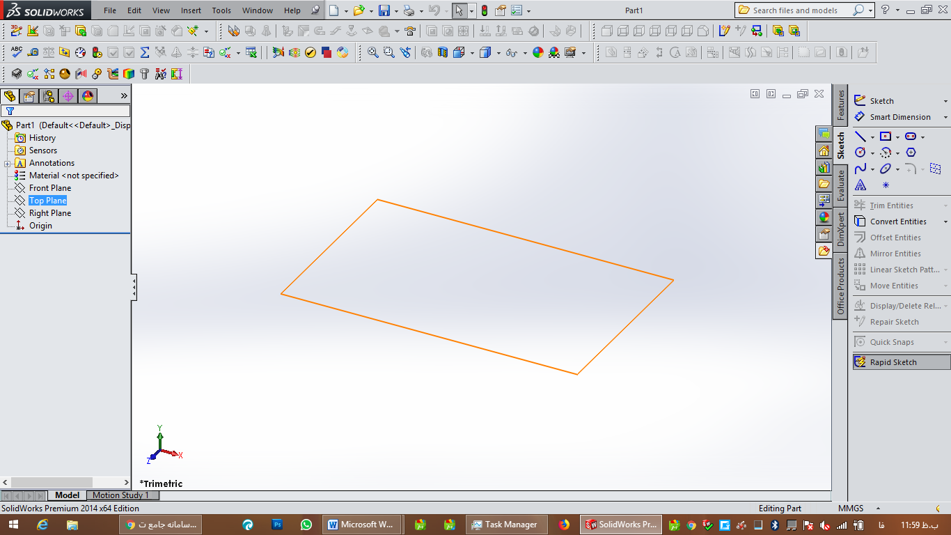
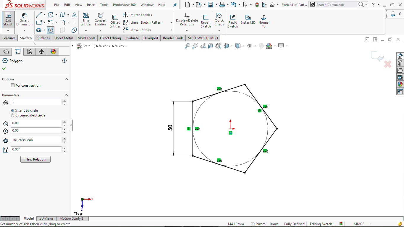
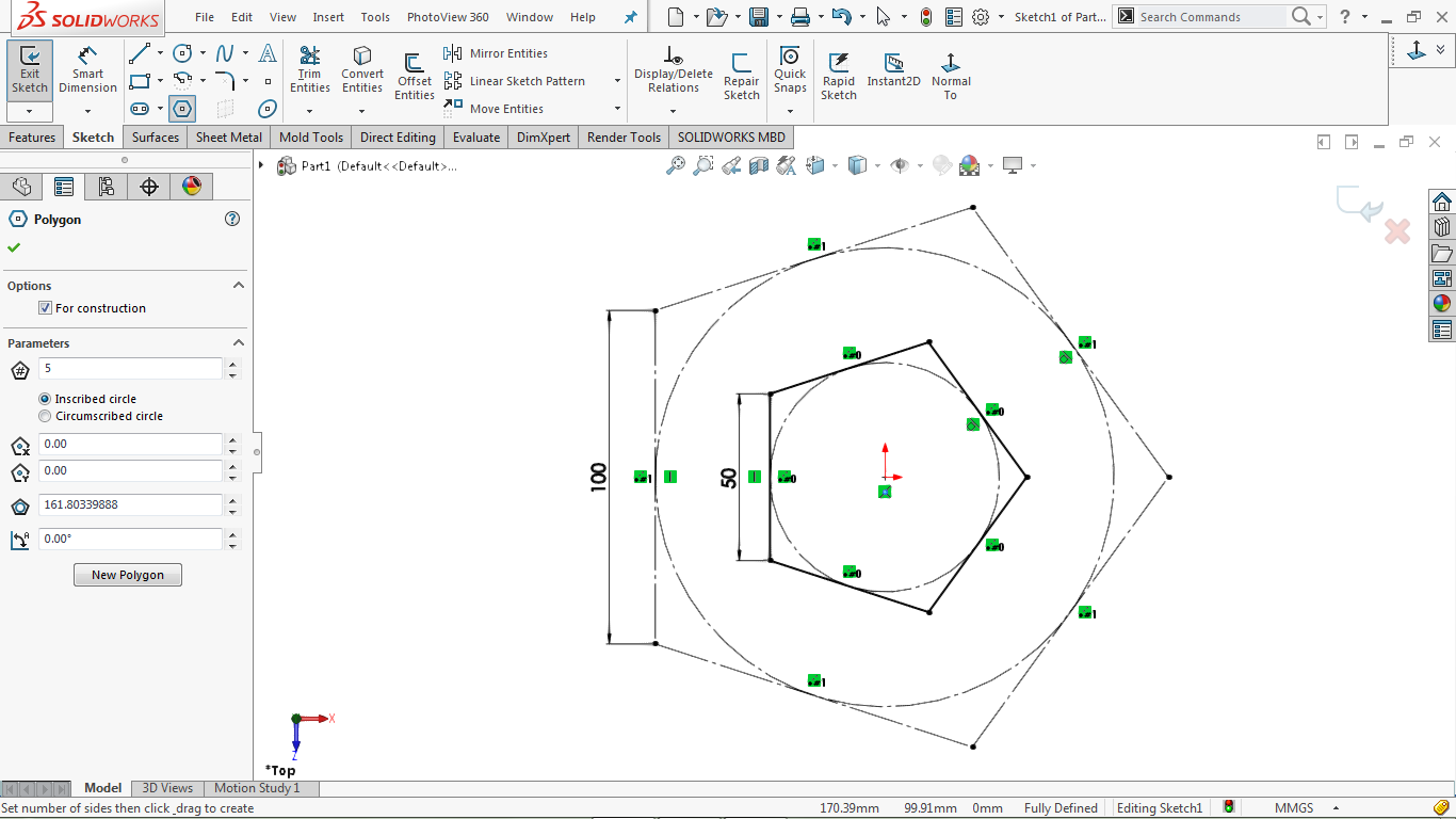
go to Tools> Sketch Entities> Polygon
Select a pentagon and draw a pentagon like the shape
Dimensions of its vertical side as follows
Go to Tools> Dimensions> Solid Polygon tool
Click on the vertical side and specify a length of 50 mm, as shown in the image below
Go to Tools> Sketch Entities> Polygon
Draw another pentagon in the center
Measure the vertical side as shown below
Go to Tools> Dimensions> Solid Polygon tool
Click on the vertical line and specify a length of 100 mm, as shown in the image below.
Click the Close sketch icon.
Create a two-dimensional sketch on the front plant
Select the front part of the feature tree and click on the sketch icon
Go to Tools> Entities Sketch> Centerline center line
Select the vertical line as shown and draw a diagonal line and draw two diagonal lines that intersect at the corners of the pentagons.
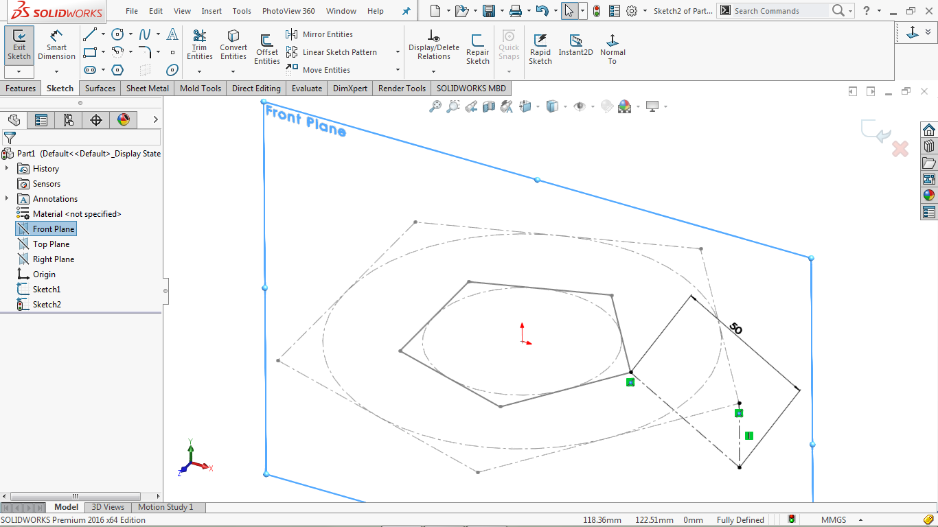
Go to Tools> Dimensions> Solid Polygon tool
Click on the diagonal line and specify a length of 50 mm.
Click Close Sketch close sketch to close the design area.
Create a Reference Plan.
Go to Insert> Geometry Reference> Plane
Click on both lines
Selected lines in purple and pink, as shown in the image below:
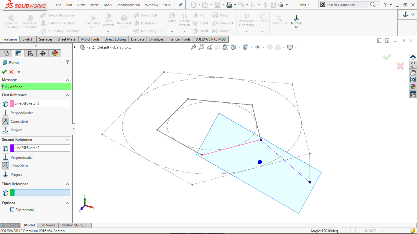
Click Ok to complete the operation.
Create a 2D layout in Plane1
Select Plane1 from the attribute tree and click on the design icon
Click the Normal to icon
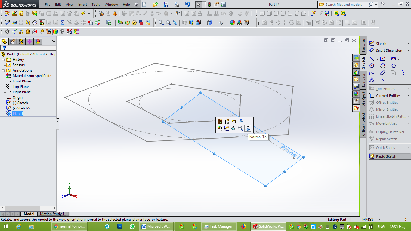
Go to Tools> Sketch Entities> Polygon
Design a polygon with 6 sides instead of 5.
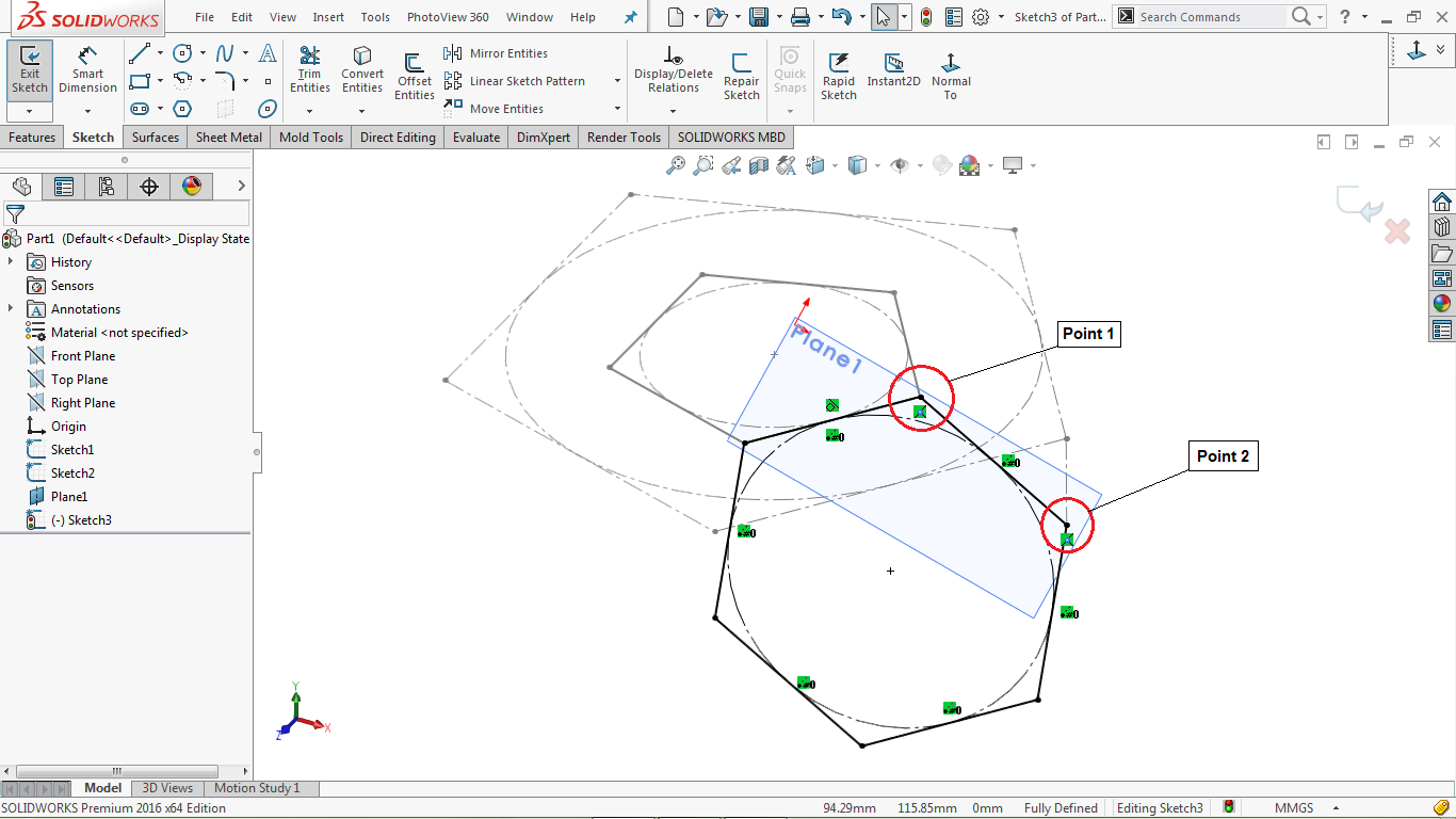
Hold down the CTRL key, select the hexagon corner and point 1
Then add a coincident relationship between them (in the properties field you must select this option)
Hold down the CTRL key, select the corner next to the hexagon and point 2
Then create a coincident relationship between them, as shown in the image below
Click Close sketch to close the design area.
Create a reference axis
Go to Insert> Geometry Reference> Axis
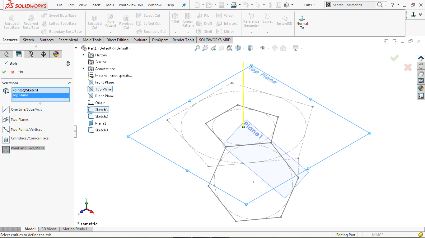
Select the “Point and Face / Plane Point” option
Click on the center point of the pentagon and select the design above
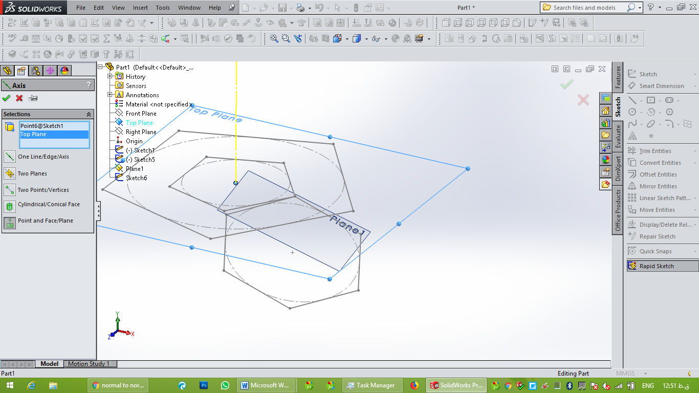
A yellow axis is highlighted, as shown in the image below:
Click OK to complete the operation.
Create a second reference axis.
Go to Insert> Geometry Reference> Axis
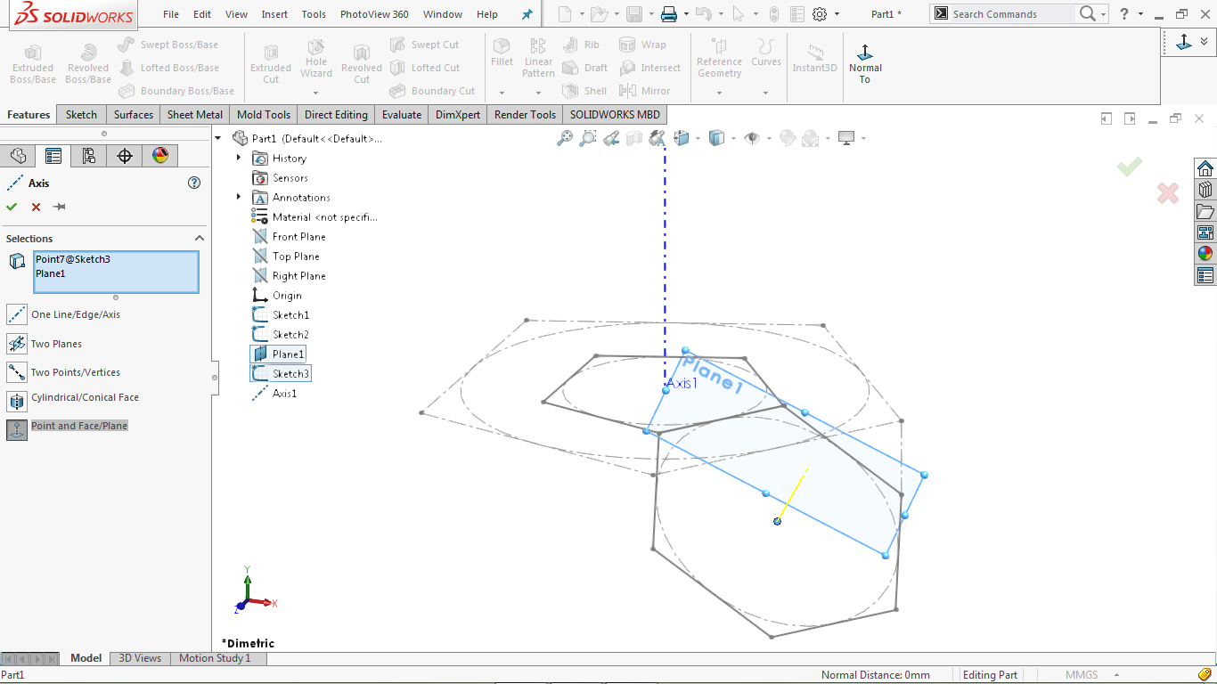
Select Point and Face / Plane.
Click on the center point of the hexagon and select Plane1.
An axis is highlighted in yellow, as shown in the image below:
Click OK to complete the operation.
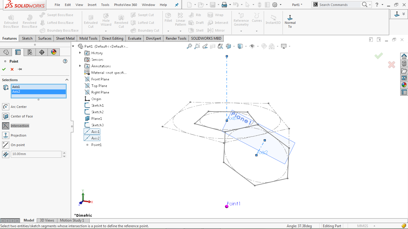
Create a reference point.
Go to Insert> Geometry Reference> Point
Select the Intersection option.
Click on Axis1 and Axis2 to create an intersection point (Point1)
The intersection point is in purple, as highlighted in the image below:

Click Ok to complete the operation.
Create a second reference point.
Go to Insert> Geometry Reference> Point… Reference Point
Select the Intersection option
Click on Axis1 and Axis2 to create an intersection point (Point2)
The intersection point is in purple, as highlighted in the image below:
Click Ok to complete the operation.
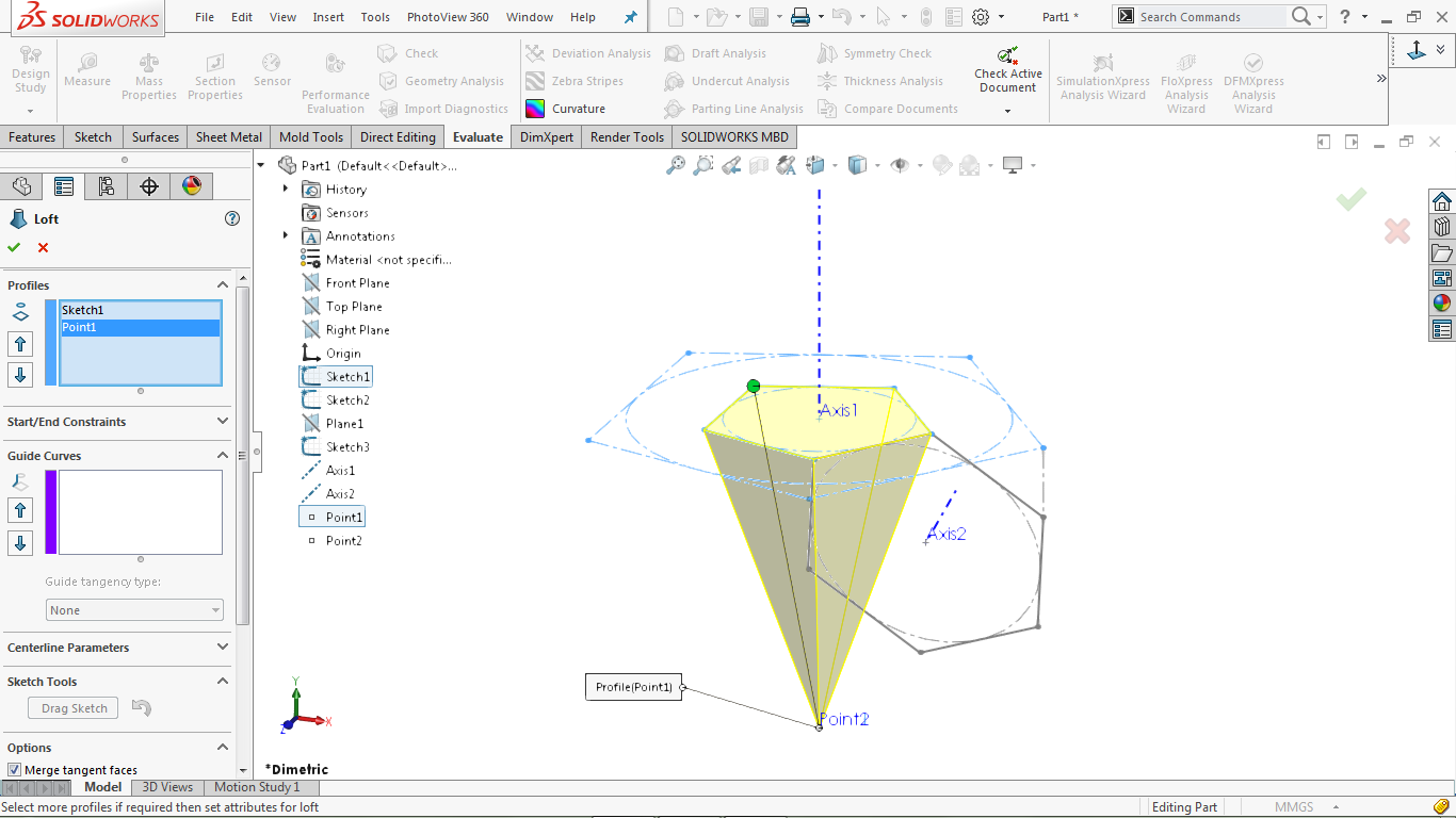
Create a lift
Go to Insert> Boss / Base> Loft
Select Sketch1 and Point1 from the attribute tree
The selected profiles create a conical geometry, as shown in the image below:
Go to Insert> Boss / Base> Loft
Select Sketch2 and Point2 from the attribute tree
The selected profiles create conical geometric profiles in the modeling area
In Property manager> Options
Uncheck the Merge Results box as shown in the image below:
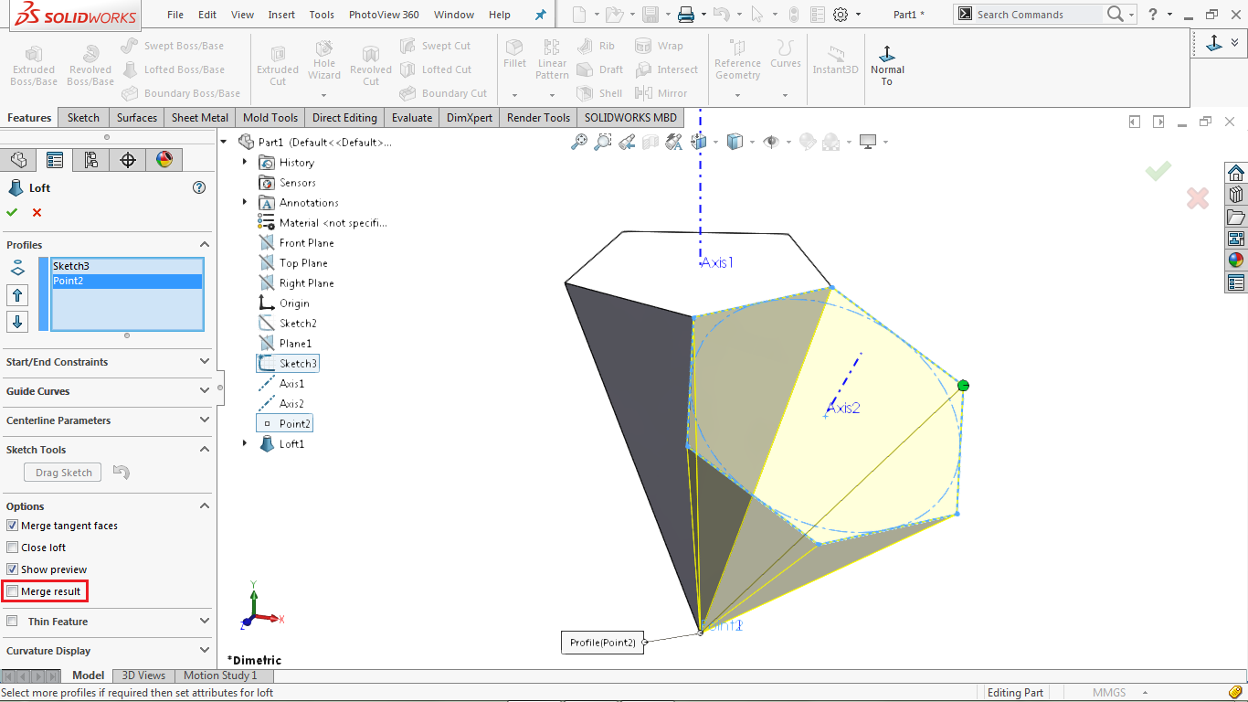
Click OK to complete the operation.
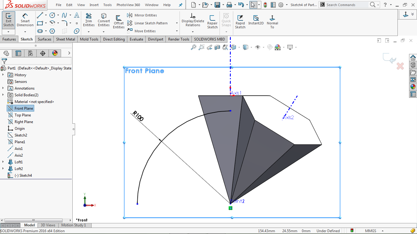
Create a two-dimensional plan in the front plan.
Select the front plan section from the Features tree and click.
Go to Tools> Sketch Entities> Center Point Arc
Draw a quarter of a circle to the center of point 1.
Go to Tools> Dimensions> Solid Polygon tool
Click on the arc and specify a radius of 100 mm for it, as shown in the image below:
Go to Tools> Entities Sketches> Offset
Select the arc and set an output offset at a distance of 10 mm, as shown in the image below:
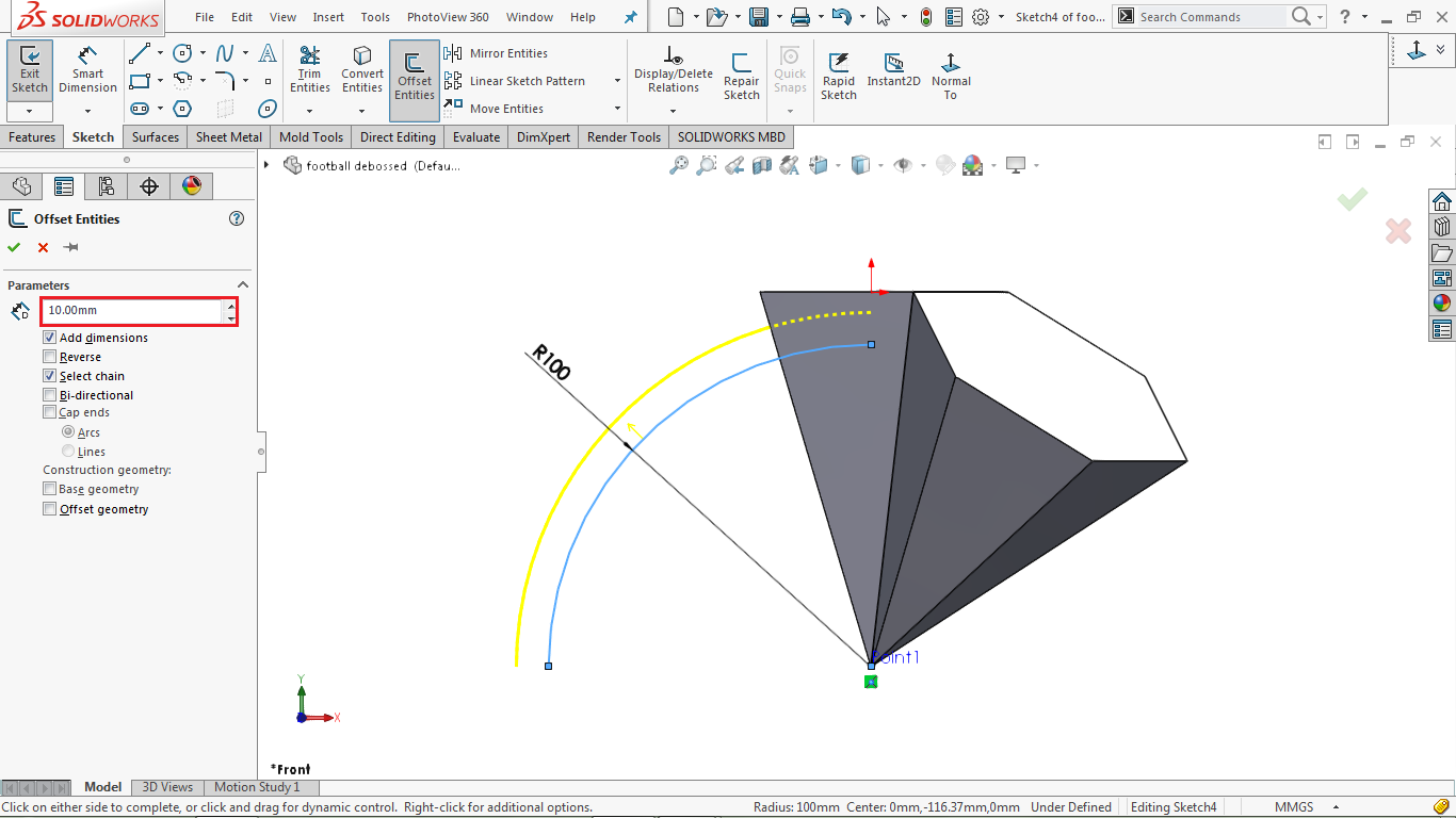
Click OK to complete the operation.
Go to: Insert> Surface> Revolve or click on Revolved Surface directly
And Go to the property manager and select the axis of a rotation axis in the revolution Axis
Then Go to the property manager section and click on the Solidworks Contour check box
Return to the modeling area and select both arcs as shown in the image below:
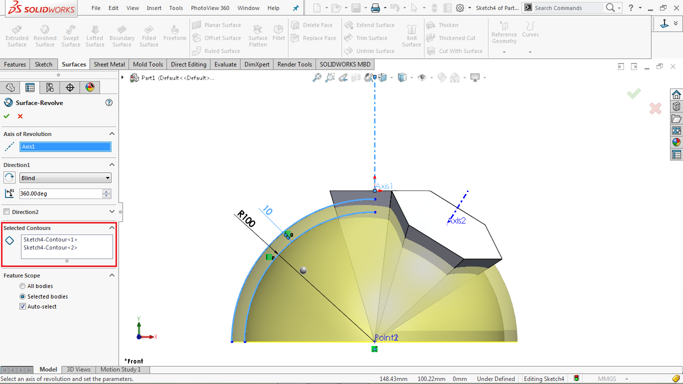
Click Ok to complete the operation.
Use the Cut With Surface tool as follows
Go to Insert> Cut> With Surface :
Select the light surfaces in the modeling area, as shown in the image below:
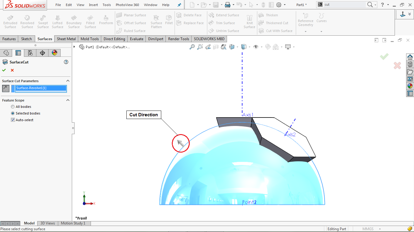
Go to the property manager and click on the Flip direction icon
Other options remain by default
Click OK to complete the operation.
Use the Cut With Surface tool as follows
Go to Insert> Cut> With Surface…
Select the inner surface of the highlight from the modeling area, as shown in the image below
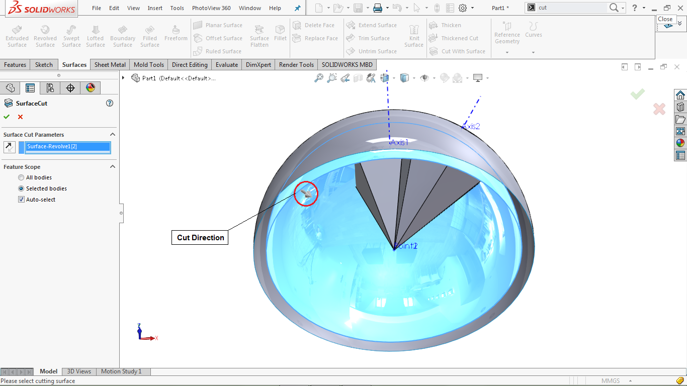
Other options remain by default
Click OK to complete the operation.
Make the shell as follows
Go to Insert> Features> Shell
To Go to property manager and set the shell thickness to 4 mm
Return to the modeling area and select the top side of the pentagon
The selected face is shown in blue, as shown in the image below.
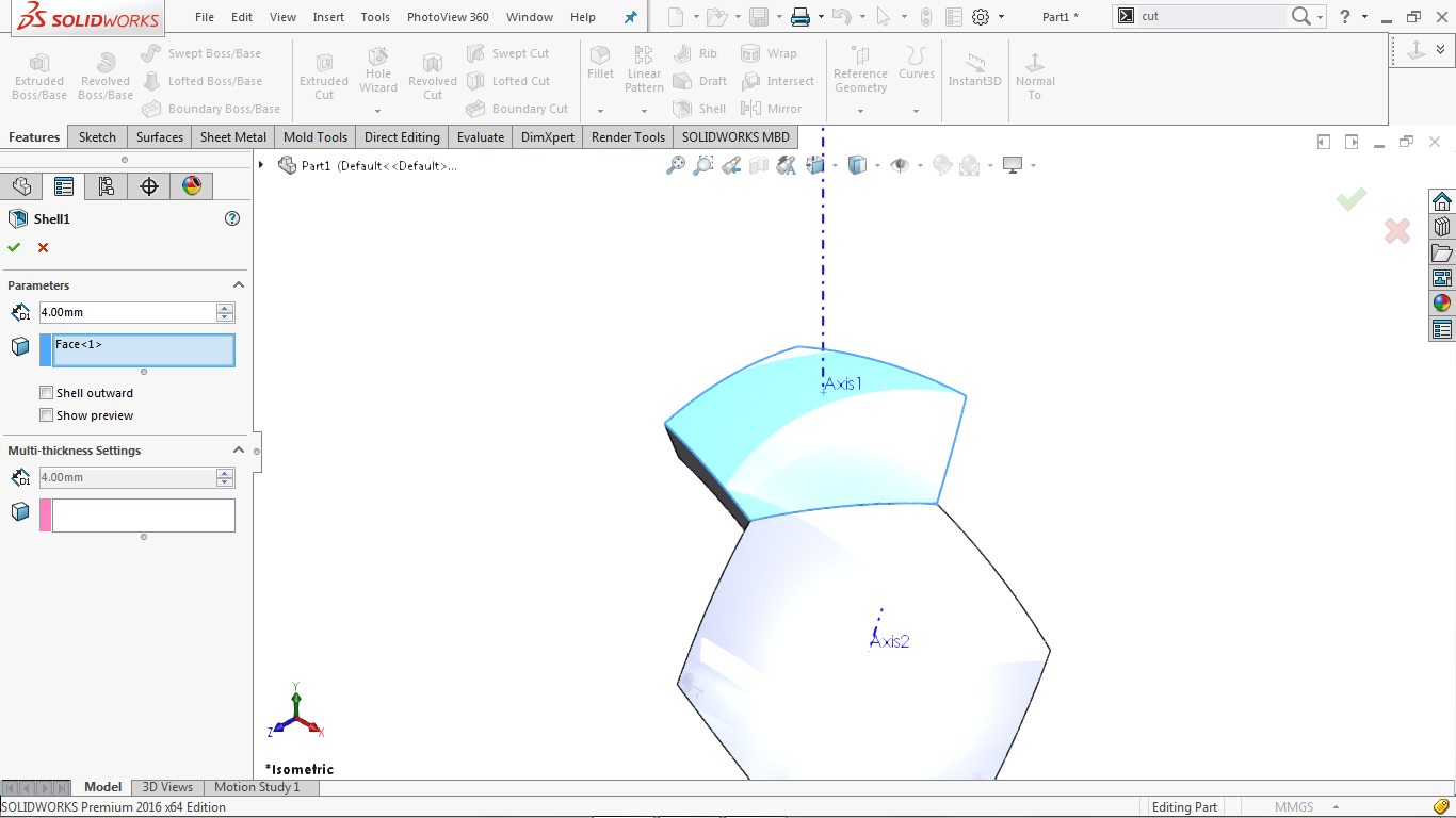
Click Ok to complete the operation.
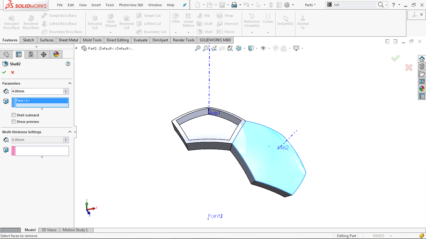
Go to Insert> Features> Shell
Go to the property manager and set the shell thickness to 4 mm
Return to the modeling area and select the top side of the hexagon
The selected face is shown in blue, as shown in the image below.
Use the fillet command as follows
Go to Insert> Features> Fillet / Round solids Fillet
Select the five inner edges of the pentagonal body, as shown in the image below
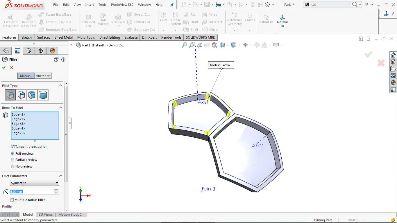
Go to the property manager and set the Fillet radius to 2 mm
Click OK to complete the operation.
Make another fillet
Go to Insert> Features> Fillet / Round solids Fillet
Select the six inner edges of the hexagonal body, as shown in the image below
The selected face is highlighted in blue, as shown in the image below
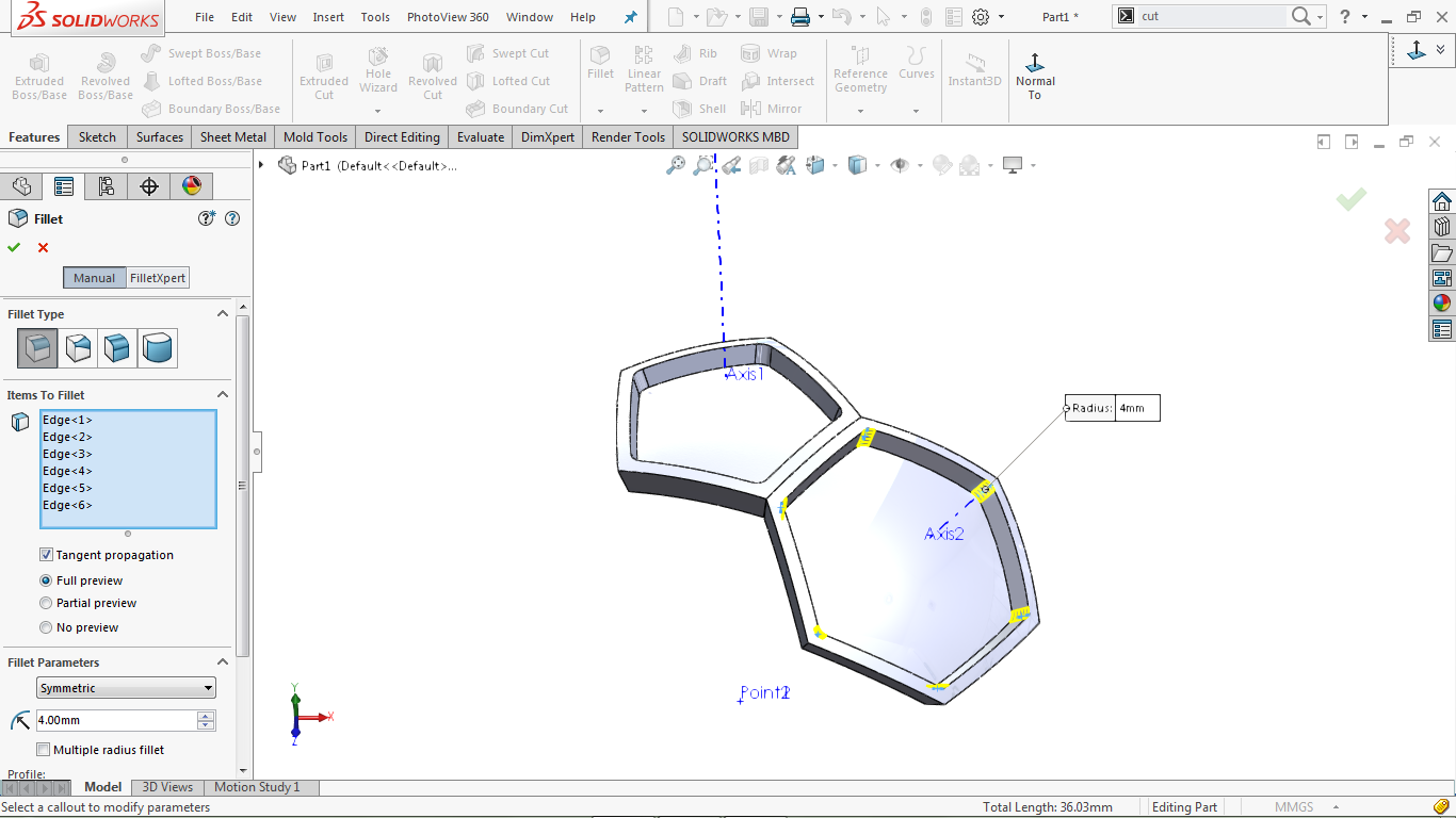
Go to the property manager and set the Fillet radius to 2 mm
Click OK to complete the operation.
Make another fillet
Go to Insert> Features> Fillet / Round solids Fillet
Select the interior surface of the pentagonal bed
The selected face is highlighted in blue, as shown in the image below
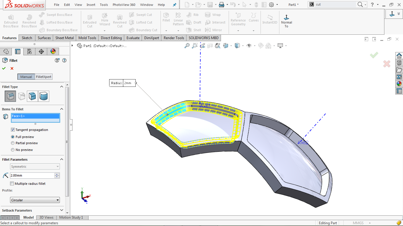
To Go to property manager and set the Fillet radius to 2 mm
Click Ok to complete the operation.
Make another fillet
Go to Insert> Features> Fillet / Round solids Fillet
Select the interior surface of the hexagonal bed
The selected face is highlighted in blue, as shown in the image below
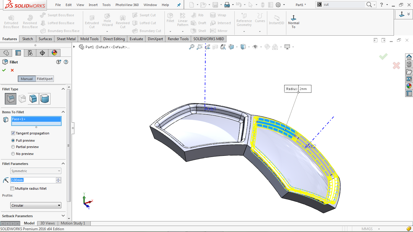
To Go to property manager and set the Fillet radius to 2 mm
Click Ok to complete the operation.
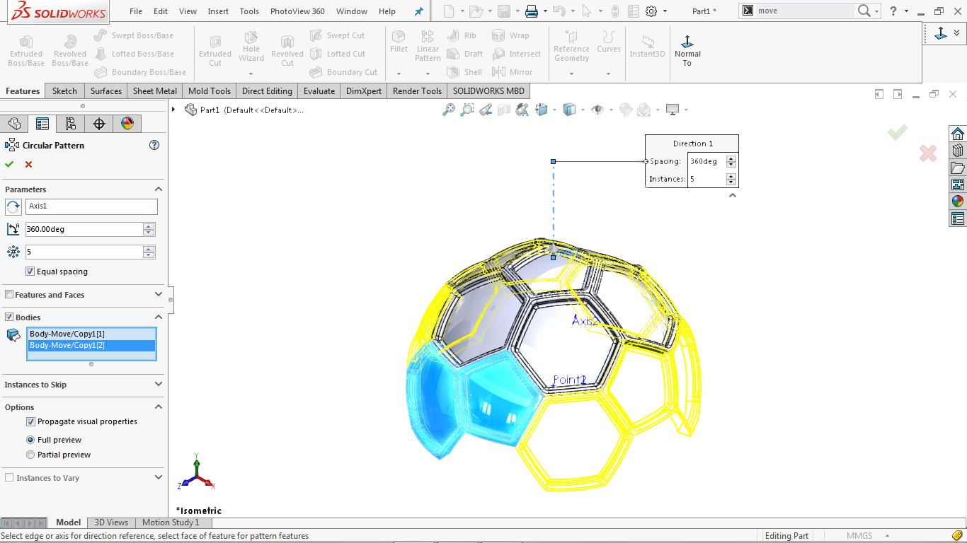
A circular pattern
Go to Insert> Pattern / Mirror> Circular Pattern
Select axis 1 as the orientation reference parameter
Set the sample size to 5 and the distance to 360 degrees
In the property manager section, select bodies
Select the hexagonal modeling area, as shown in the image below
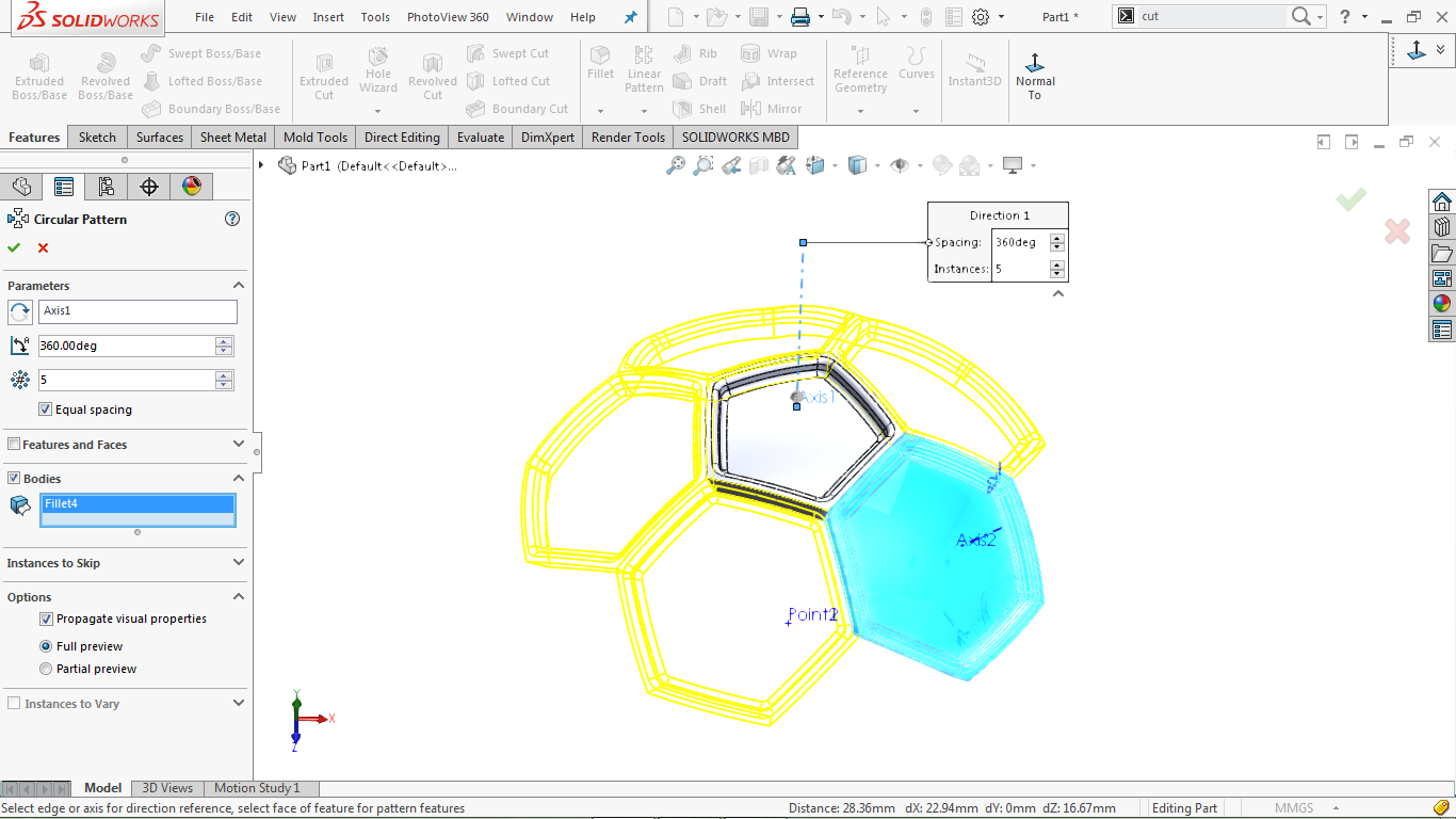
Click OK to complete the operation.
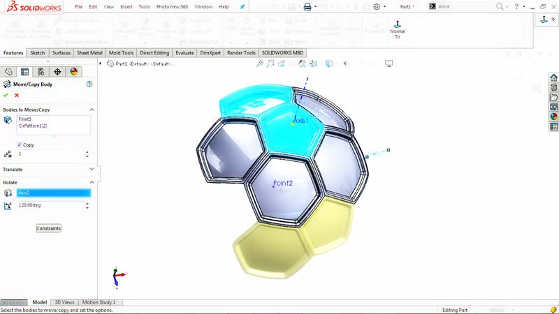
Use the Move / Copy Body Tool
Go to Insert> Features> Move / Copy
Select pentagon and hexagon from the modeling area
Go to the property manager and activate the copy option and write the number of copies of copies as 1
The selected body is shown in blue as shown in the image below
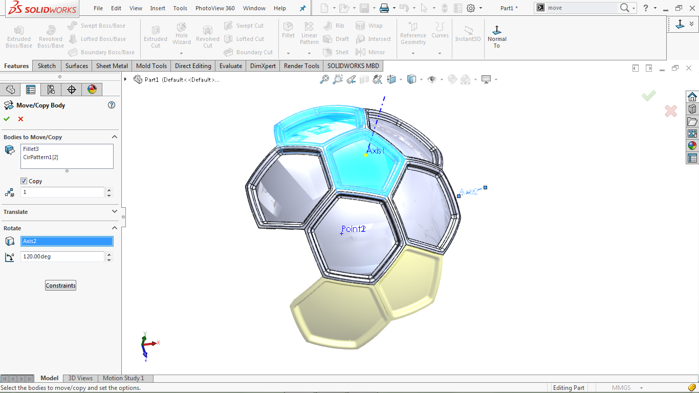
Click the Rotate box at the bottom of the property manager
Go to the modeling area and select Axis2 (axis 2) as the reference axis
Set the amount of rotation in the rotation amount box to 120 degrees
Click OK to complete the operation.
Create a circular pattern
Go to: Insert> Pattern / Mirror> Circular Pattern
Select Axis1 (axis 1) as the reference reference parameter
Set the sample size to 5 and the distance to 360 degrees
Go to property manager, select Bodies
Go to the modeling section and select the copied hexagonal and pentagonal body
The selected body is shown in blue as shown in the image below
Click OK to complete the operation.
Use the Combine feature
Go to Insert> Features> Combine :
Select the sixteen available sections from the modeling area
Go to property manager and click add
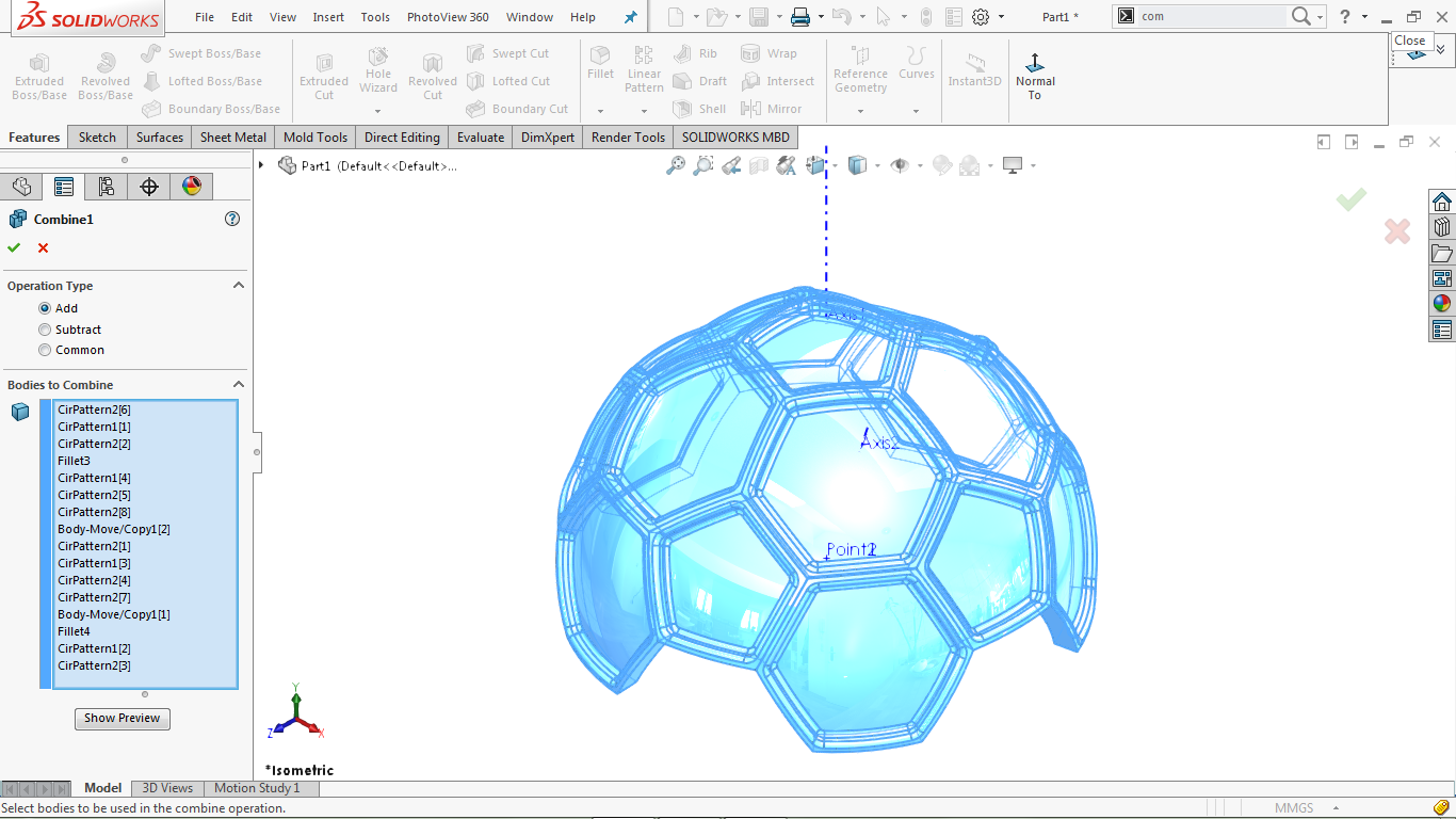
Click OK to complete the operation.
Use the Move / Copy Body Tool
Go to Insert> Features> Move / Copy
Select the combined body from the modeling area
To Go to property manager and click on the rotate reference box
Go to the modeling area and select Point1 or Point2 as the rotation reference
Assign the amount of rotation around the X, Y and Z axes as follows
X = 0 degrees, Y = 0 degrees, Z = 180 degrees
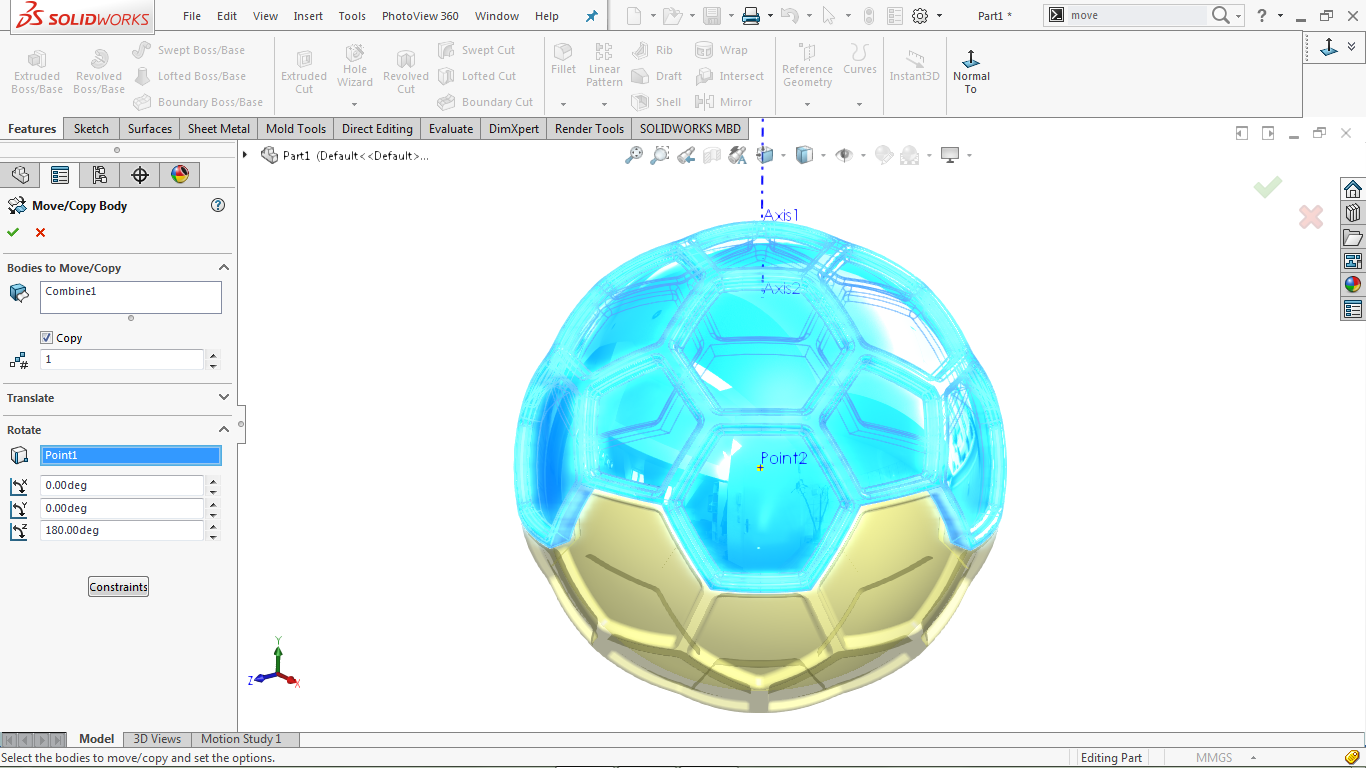
Set other values by default
Click OK to complete the operation.
Use the blend feature
Go to Insert> Features> Combine Combine
Select both combinations from the modeling area
To Go to property manager and click add
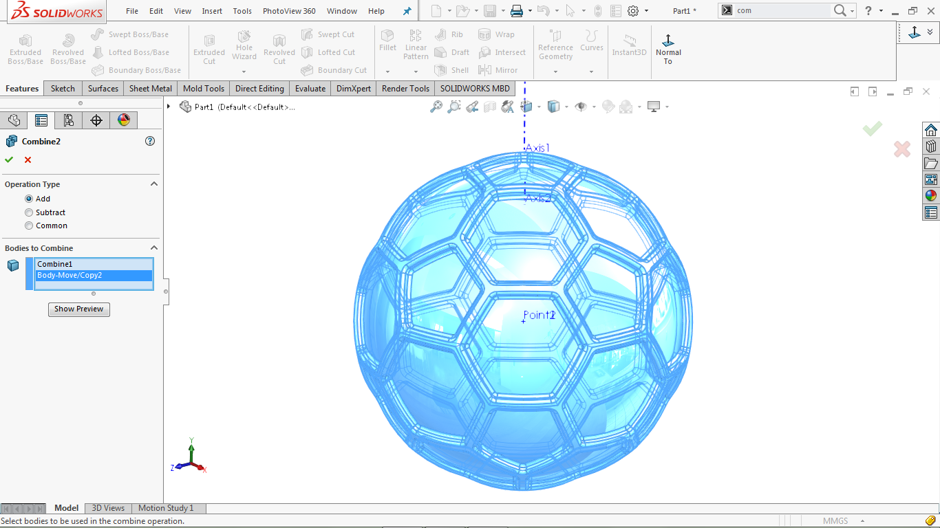
Click OK to complete the operation.
Create a 2D sketch in Front Plane
Select the Front Plane section from the feature tree and click on its icon
Go to: Tools> Sketch Entities> Center Point Arc
Draw a semicircle to the center of point 1 (or point 2)
Go to Tools> Entities Sketch> Center line center line
Draw a vertical line to close the semicircle as shown in the image below
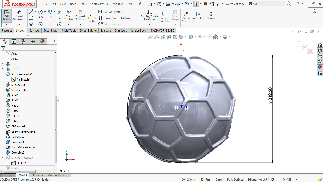
Go to: Tools> Dimensions> Solid Polygon tool
Select the construction line and set its length to 212.50 mm
Click the Close icon to close the sketch.
Create a rotating surface
Go to Insert> Surface> Revolve
Go to property manager and select axis 1 as the rotation axis
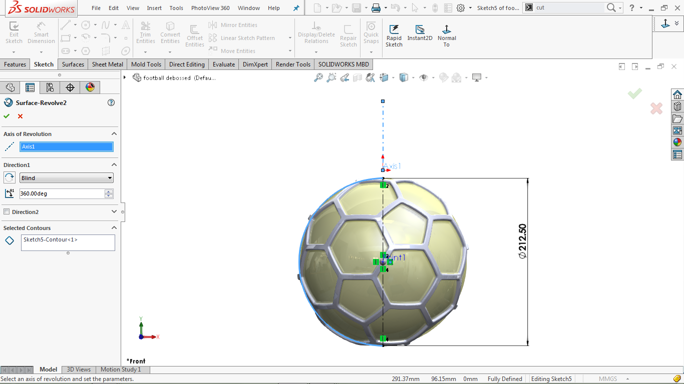
Click OK to complete the operation.
Use the Split feature
Go to Insert> Molds> Split
Go to property manager and then log in to Trim Tools
Select Surface Revolve2 from the Properties tree
Go to Property manager> Target Bodies
And Go to the modeling area and select the body (Combine2)
Then Go back to the Target Bodies option and click on Cut bodies to split it
Go to Property manager> Resulting Bodies
Select both files from the dialog box, as shown in the image below
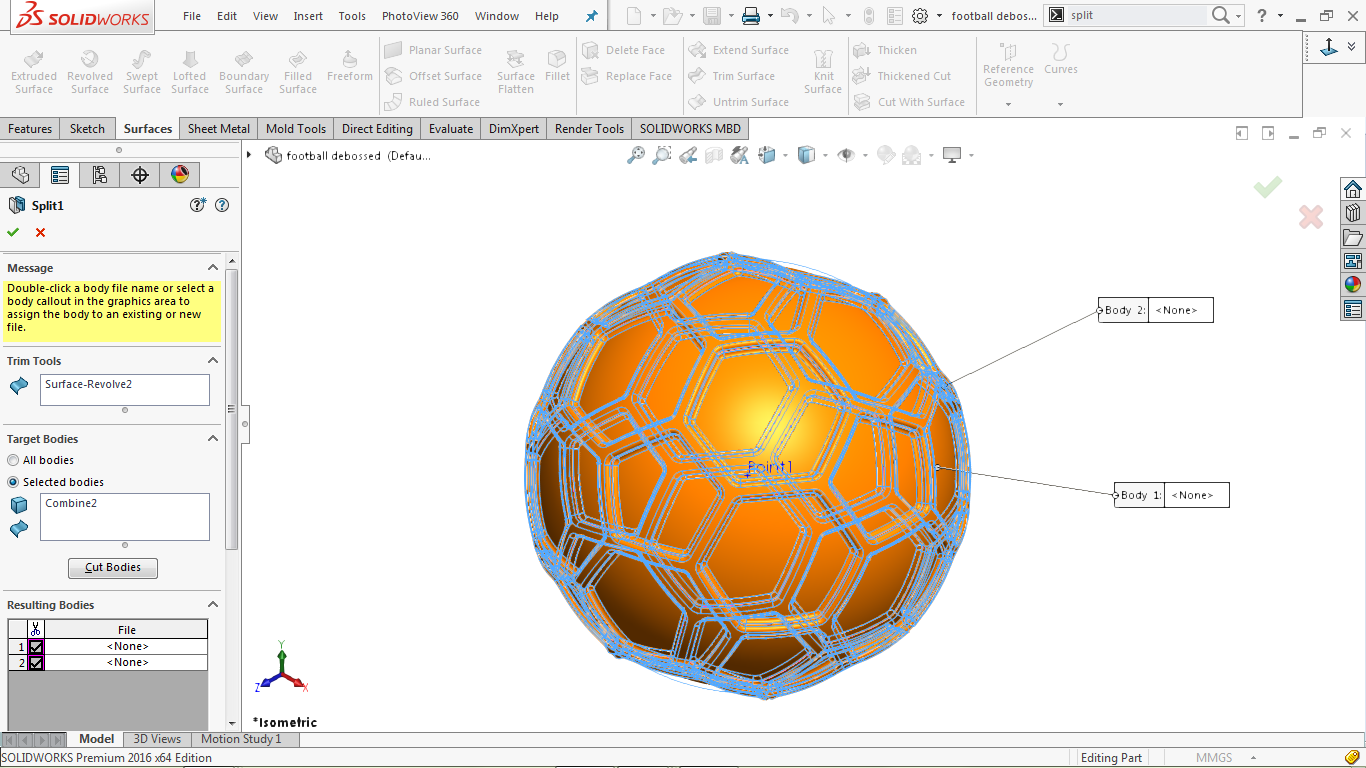
Click OK to complete the operation.
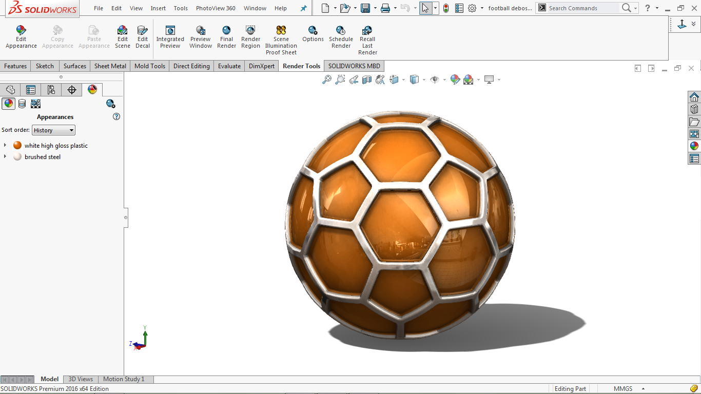
Change the appearance
Go to PhotoView 360> Edit Appearance
Go to the property manager and right-click on the Selected Geometry dialog box
Click Clear Selections to clear the dialog box
Click on the Select Bodies icon
Go to the modeling area and select the interior area
Go to: Appearances (color)> Plastic> High Gloss> White High Gloss Plastic
To Go to property manager and select orange, as shown in the image below
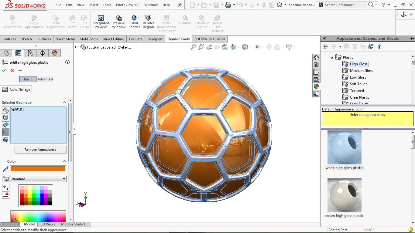
Click OK to apply the changes.
Go to PhotoView 360> Edit Appearance
Go to the property manager and right-click on the Selected Geometry dialog box
Click Clear Selections to clear the dialog box
Click on the Select Bodies icon
Go to the modeling area and select the outer part
Go to: Appearances (color)> Metal> Steel> Brushed Steel
Double-click the Brushed Steel icon to apply the selected look
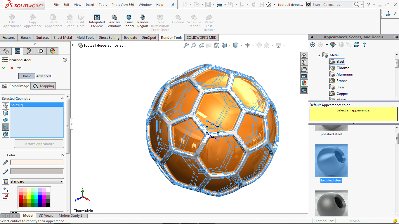
Click OK to complete the operation.
Go to: View> Display
Select Shaded mode and then Shadows In Shaded Mode and then Ambient Occlusion if possible.
The final figure is shown in the image below