


Introduction To Arduino mega 2560 Board
What Is Arduino Mega?
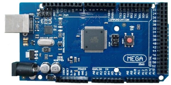
The Arduino Mega 2560 is a microcontroller board reliant on the ATmega2560. It has 54 automated input/output pins (of which 15 can be used as PWM outputs), 16 basic inputs, 4 UARTs (hardware successive ports), a 16 MHz valuable stone oscillator, a USB affiliation, a power jack, an ICSP header, and a reset catch.
It contains everything expected to help the microcontroller; simply partner it to a PC with a USB connection or power it with an AC-to-DC connector or battery to start.
The Mega 2560 board is acceptable with most shields proposed for the Uno and the past boards Duemilanove or Diecimila. The Mega 2560 is an update to the Arduino Mega, which it replaces.
Arduino is an open-source physical registering stage dependent on a basic I/o board and an improvement domain that actualizes the Processing/Wiring language. Arduino can be utilized to create remain solitary intuitive items or can be associated with programming on your PC (for example Streak, Processing, MaxMSP). The open-source IDE can be downloaded for nothing (as of now for Mac OS X, Windows, and Linux).
The Mega 2560 R3 likewise includes SDA and SCL pins by the AREF. Likewise, there are two new pins set close to the RESET pin. One is the IOREF that enables the shields to adjust to the voltage gave from the board.
The other is not associated and is saved for future purposes. The Mega 2560 R3 works with every single existing shield yet can adjust to new shields that utilize these extra pins.
What is the use of Arduino Mega?
Arduino can be utilized to create remain solitary intuitive articles or can be associated with programming on your PC (for example Streak, Processing, MaxMSP). The open-source IDE can be downloaded for nothing (right now for Mac OS X, Windows, and Linux). The Arduino Mega is a microcontroller board dependent on the ATmega2560.
Features:
ATmega2560 microcontroller
Input voltage – 7-12V
54 Digital I/O Pins (14 PWM outputs)
16 Analog Inputs
16Mhz Clock Speed
4 sequential ports
256k Flash Memory
8KB SRAM
4KB EEPROM
Programming
The Mega 2560 board can be customized with the Arduino Software (IDE). The ATmega2560 on the Mega 2560 comes prearranged with a bootloader that enables you to transfer new code to it without the utilization of an outside equipment developer. It imparts utilizing the first STK500 convention (reference, C header records).
You can likewise sidestep the bootloader and program the microcontroller through the ICSP (In-Circuit Serial Programming) header utilizing Arduino ISP or comparable; see these guidelines for subtleties.
The ATmega16U2 (or 8U2 in the rev1 and rev2 boards) firmware source code is accessible in the Arduino vault. The ATmega16U2/8U2 is stacked with a DFU bootloader, which can be initiated by:
On Rev1 boards: interfacing the bind jumper on the rear of the board (close to the guide of Italy) and afterward resetting the 8U2.
On Rev2 or later boards: there is a resistor that pulling the 8U2/16U2 HWB line to ground, making it simpler to place into DFU mode. You would then be able to utilize Atmel’s FLIP programming (Windows) or the DFU developer (Mac OS X and Linux) to stack another firmware. Or then again you can utilize the ISP header with an outside software engineer (overwriting the DFU bootloader).
Alerts
The Arduino Mega has a resettable polyfuse that shields your PC’s USB ports from shorts and overcurrent. Albeit most PCs give their own inside insurance, the breaker gives an additional layer of assurance. In the event that in excess of 500 mA is applied to the USB port, the circuit will consequently break the association until the short or over-burden is evacuated.
Power
The Arduino Mega 2560 can be fueled by means of the USB association or with an outer force supply. The force source is chosen consequently. Outer (non-USB) force can come either from an AC-to-DC connector (divider mole) or battery.
The connector can be associated by stopping a 2.1mm focus positive attachment into the board’s capacity jack. Leads from a battery can be implanted in the GND and Vin pin headers of the POWER connector.
The board can work on an outside inventory of 6 to 20 volts. Whenever provided with under 7V, be that as it may, the 5V pin may supply under five volts and the board may get shaky.
In case using more than 12V, the voltage controller may overheat and hurt the board. The recommended range is 7 to 12 volts.
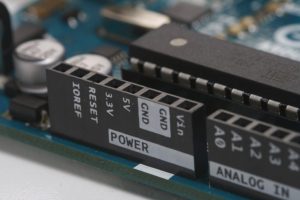
The power pins are according to the followings:
Vin: The input voltage to the board when it’s utilizing an outer force source (rather than 5 volts from the USB association or other controlled force sources). You can supply voltage through this pin, or, if providing voltage by means of the force jack, get to it through this pin.
5V: This pin outputs a directed 5V from the controller on the board. The board can be provided with power either from the DC power jack (7 – 12V), the USB connector (5V), or the VIN pin of the board (7-12V).
Providing voltage through the 5V or 3.3V pins sidesteps the controller, and can harm your board. We don’t prompt it.
3V3. A 3.3 volt supply produced by the onboard controller. The most extreme current draw is 50 mA.
GND. Ground pins.
IOREF. This pin on the board furnishes the voltage reference with which the microcontroller works. An appropriately designed shield can peruse the IOREF pin voltage and select the suitable force source or empower voltage interpreters on the outputs for working with the 5V or 3.3V.
Memory
The ATmega2560 has 256 KB of blaze memory for putting away code (of which 8 KB is utilized for the bootloader), 8 KB of SRAM and 4 KB of EEPROM (which can be examined and created with the EEPROM library).
Input And Output
Every one of the 54 computerized pins on the Mega can be utilized as an input or output, utilizing pinMode(),digitalWrite(), and digitalRead() capacities. They work at 5 volts. Each pin can give or get 20 mA as the suggested working condition and has an inner draw up resistor (separated as a matter of course) of 20-50 k ohm.
A limit of 40mA is the worth that must not be surpassed to stay away from perpetual harm to the microcontroller.
Moreover, a few pins have specific capacities:
Sequential: 0 (RX) and 1 (TX); Serial 1: 19 (RX) and 18 (TX); Serial 2: 17 (RX) and 16 (TX); Serial 3: 15 (RX) and 14 (TX). Used to get (RX) and transmit (TX) TTL sequential information. Pins 0 and 1 are additionally associated with the comparing pins of the ATmega16U2 USB-to-TTL Serial chip.
Outside Interrupts: 2 (interrupt 0), 3 (interrupt 1), 18 (interrupt 5), 19 (interrupt 4), 20 (interrupt 3), and 21 (interrupt 2). These pins can be arranged to trigger an interrupt on a low level, a rising or falling edge, or an adjustment in level. See the attachInterrupt() work for subtleties.
PWM: 2 to 13 and 44 to 46. Furnish 8-piece PWM output with the analogWrite() work.
SPI: 50 (MISO), 51 (MOSI), 52 (SCK), 53 (SS). These pins support SPI correspondence utilizing the library. The SPI pins are likewise broken out on the ICSP header, which is physically perfect with the Arduino/Genuino Uno and the old Duemilanove and Diecimila Arduino boards.
Driven: 13. There is a built-in LED associated with advanced pin 13. At the point when the pin is HIGH worth, the LED is on, when the pin is LOW, it’s off.
TWI: 20 (SDA) and 21 (SCL). Backing TWI correspondence utilizing the Wire library. Note that these pins are not in a similar area as the TWI pins on the old Duemilanove or Diecimila Arduino boards.