3 Great Solutions For Modeling And Molds To Increase The Speed Of Working With Solidworks
Avoiding repetitive tasks can often be one of the easiest ways to facilitate and expedite work. While things are not always easy at SolidWorks, there are simple ways to reduce the difficulty.
Many times we start a new project and do not realize that we are doing a lot of repetitive work. To avoid this and save time, you can create templates for parts, assemblies and design sketches, but there is a secret.
What is an idea?
The idea behind each template is to have an original version of everything you create that you can use with the new version at different times when you need it again. Here’s how to do it.
Templates are actually solidwork documents. Each time you select File, you can select New, Section, Assembly, or Drawing by selecting New. These are the same patterns; So, can’t they be made a little more advanced to help you speed up your design? This is possible.
Create a document with the most general information possible. It doesn’t matter if the part is assembly or drawing, we want it to be clean and tidy.
Parts – Put limited features in the file. For example, if the output mold is extruded, just create the base shape without specifying angles, holes, or cuts. You only add another feature if you want to use it specifically.
Assembly – How can you create a basic assembly? This is really simple. For example, just create an external model and add internal details and components at the time of use.
Drawings and Maps – We can typically use BOMs as templates by adding things to them, even parts and assemblies, something I always create, template design for Public notes. I can create this as a block.
Important Note: Be sure to include all proprietary data along with the copyright notice and all relevant information in the template.
Where do I save the template?
The default location in the data folder is the SolidWorks installation folder, but you can place them anywhere you like.
I recommend creating a network folder with separate subdivisions to organize your file types.
Anything that can create a basic and versatile version from scratch can be a template. Here are some other examples of documents that you can turn into templates and templates.
Parts include: extrusion, metal consumables, studs, sheet metal boxes, gears, ergonomic surfaces, buttons
Assemblies include: pallet sets, sliders, chassis, circuit boards, internal system components
Drawings and Drawing include: general notes, installation drawings, wiring diagrams, plumbing commissioning drawings
Method of layout and arrangement of three-dimensional models
Creating a way to lay out and organize designed models can be daunting. A modeling approach defines how you build your models and keep them compatible with your company system.
If you work for a design company with SolidWorks, you may have learned some modeling techniques. However, if you are new or trying to create a modeling and layout method, where do you start? This article outlines three ways to start modeling and group organizing.
Bottom-up or part-to-whole methods are very common, but are there any methods that can work better? Here are three unique approaches that may provide the solution to define a better approach for your team.
Definition of body and part
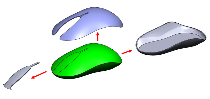
Objective: To speed up the work, in order to develop the concepts, all the components in a file are modeled, which increases the speed and reduces the number of files.
way of doing:
- Perform all drawings in one section
- Uncheck Merge Results when creating each feature (anything in the tree diagram to the left of the feature tree is a feature)
- Right-click on the Solid Bodies folder, select Save Bodies and Create Assembly
What does it do then? When you save bodies as parts of an assembly file, you can easily control the assembly parts of a unit.
Disadvantages: Unable to change parts and assembly at the same time.
Assembly sketch method
Objective: Use a single sketch (initial and quick design) to define the relationships between the components, which leads to the reduction of dead bodies and automatic design.
way of doing:
- Create a part file or assembly that contains only sketches or sketches.
- Insert this file into the assembly.
- Enter the parts and define them using designs only.
What is the benefit of this action? This is a top-down approach and lets you control everything about the design. If a part changes, other parts will not be affected. Everything is derived from a sketch.
Disadvantages: It is difficult to create movement in the assembly
Enter a model or template
Objective: To simplify component configuration and define properties and weight
way of doing:
- Import the model
- Simply configure it
- Add properties and weight to it
What does it do? Allows you to use a complex task to make your task easier. This feature can be used for parts purchased or models extracted from a different system. You can also export your models, import them into other projects, and do so to reduce file size, but you will lose all your features.
Disadvantages: Makes multiple settings difficult.
What should I do next Modeling ?
Here are five steps you can take to begin the process of preparation for mediation.
- Turn it into a working document.
- Consider a quick guide to it.
- Check and edit it.
- Distribute it among the team.
- Make sure everyone understands and understands it.