Mechanism of Layer 2 Switches & How to Secure Their Ports
Layer 2 Switches: We use a switching technique to divide large collision domains into smaller domains so that two or more devices with the same bandwidth are placed in their own environments.
Hub-based networks are an excellent example in this field, but hubs have been replaced by a more advanced model called a switch because they waste network bandwidth and cause other problems.
Since each switch port has its own collision domain, hubs have gradually been replaced by switches to implement more stable and secure networks.
Switches have entirely changed the way networks are designed and implemented.
What is the difference between the functional mechanisms of bridges and switches?
As you can see, these two network hardware are technically significantly different. Bridges use software to create and manage a Content Addressable Memory (CAM) filter table. In contrast, the fast switches we use today use Application-Specific Integrated Circuits (ASICs) to build and maintain MAC filter tables. Still, they have the same functionality, and we are not wrong if we describe a layer two switch as a multiport bridge because both hardware are used to break collision domains.
Layer 2 switches and bridges are faster than routers because they don’t waste time checking network layer header information. Instead, they look at the frame’s hardware addresses before deciding whether to send or discard the frame. Unlike hubs, switches create dedicated and private collision domains and provide independent bandwidth per port.
When you use Layer 2 switching, you get four essential benefits:
- Hardware-based bridging (ASIC).
- Achieve the highest transmission speed.
- Low latency.
- Low implementation cost.
In layer two switching, no changes are applied to the data packet, which plays a vital role in the fast transmission of information packets because the switch only reads the encapsulating frame of the packet. As a result, more minor routing errors are encountered.
In addition, if you use Layer 2 switching for workgroup connectivity and network segmentation (collision domains separation), you can create more segments in the network, resulting in optimal bandwidth utilization. Another excellent benefit of Layer 2 switching is that more bandwidth is available to users because each device connected to the switch has its own independent collision domain.
Three essential functions of layer two switches
Layer 2 switching provides the three essential capabilities of learning addresses, making forwarding or filtering decisions, and avoiding loop problems.
- Address Learning: Layer 2 switches remember the hardware address of the source that sends them a frame through the network interfaces and store that information in a MAC database called the forward/filter table. In the past, this table was called Content Addressable Memory CAM.
- Forward/Filter Decisions: When deciding whether to forward or filter a frame it receives from an interface, the switch looks at the destination hardware address and searches the MAC database to find the appropriate outgoing interface. In this case, the frame is sent only to the destination port, and like the hub, not all ports will receive the frame.
- Loop avoidance: If multiple connections are made between switches to achieve the principle of redundancy, the possibility of loop occurrence is high. Network experts use Spanning Tree Protocol (STP) to solve this problem. The above protocol allows you to implement the principle of redundancy in connection with switches and not worry about the occurrence of ring problems.
Now that we have provided a brief explanation of the three critical capabilities of Layer 2 switches, it is time to examine each of these functions in more detail.
Learn the address
The MAC address table is empty when a switch is powered off. Figure 1 shows this situation.
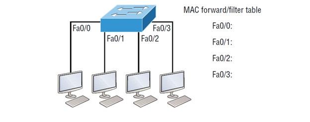
Figure 1
When a network device sends a packet, and an interface receives a frame, the switch enters the frame’s source address into the forwarding/filter table to obtain detailed information about the device that sent the frame. In the first routing step, the switch has to use the frame flooding technique for all interfaces connected to the button to find the frame’s destination because it has no idea where the destination device is located in the network.
If a device responds to this frame with a flooded message and sends a reply frame, the switch receives the frame’s source address and adds it to its MAC address database. In this case, the above address corresponds to the address of the interface that received the frame. Since the switch now has both relevant MAC addresses in its filter table, the two devices can establish a point-to-point connection. Like the first time, the controller no longer needs to send the frames of these two devices to all ports because it has information related to these two devices. That’s why layer two switches work smarter than hubs. In a hub-based network, whenever any device sends a frame, it is sent to all ports because the hub does not have a database to store the hardware information of the devices. Figure 2 shows the process of building the MAC addresses database.
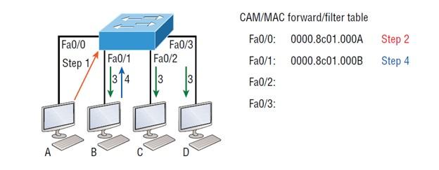
Figure 2
In Figure 2, you can see four hosts connected to a switch. When the switch is first powered on, as shown in Figure 1, it does not have any addresses, and the forwarding/filter table is empty. Still, when the hosts start communicating, the switch displays the hardware address of the source of each frame, along with the port to which the frame’s source address belongs. It matches in the table.
The processes performed in Figure 2 are as follows:
- Host A sends a frame to host B. The MAC address of host A is 0000.8c01.000, and the MAC address of host B is 0000.8c01.000.
- The switch receives the frame on interface Fa0/0 and places the source address in the MAC address table.
- Since the destination address is not in the MAC database, the frame is forwarded to all interfaces except the source port.
- Host B receives the frame and responds to host A. The switch receives this frame on interface Fa0/1 and puts the source hardware address into the MAC database.
- Now, host A and host B can establish a point-to-point connection, and when they send a frame to each other, the other devices will not receive it. More specifically, hosts C and D are not receiving frames, and naturally, their MAC addresses are not found in the database because they have not yet sent an edge to the switch.
If host A and host B do not communicate with the switch for a long time, the controller deletes their entries from the database so that the database table is not occupied unnecessarily.
Sending and filtering decisions
When a frame arrives at a switch interface, the destination hardware address is compared to the MAC database to apply a forwarding or filtering process to the edge. The frame is sent to the appropriate output interface if the destination hardware address is known and in the database. In this case, the switch does not forward the frame to any interface other than the destination interface to conserve network bandwidth. This process is called “frame filtering.”
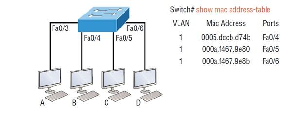
Figure 3
If the destination hardware address is not in the MAC database, the frame is sent based on the flooding technique to all active interfaces except the one that is the source. If a device responds to a flooded frame, the MAC database information is updated with the location of the device and its associated interface.
If a host or server sends a broadcast message on the LAN, the switch will default flood the frame to all active ports except the source port. Note that the controller creates smaller collision domains, but by default, it creates a large playback domain. In Figure 3, host A sends a data frame to host D. What does the switch do when it receives the frame from host A? To find the answer, look at Figure 4.
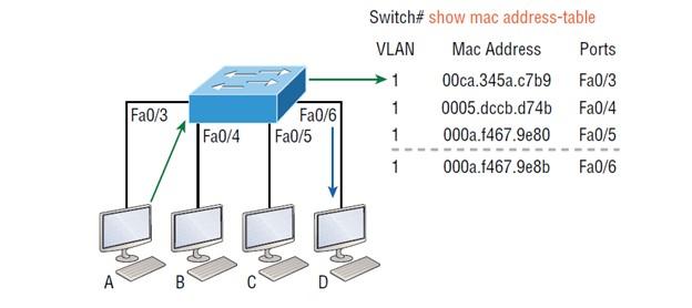
Figure 4
Since host A’s MAC address is not in the forwarding/filter table, the switch adds the source and port address to the MAC address table and forwards the frame to host D. Note that the controller first checks the MAC address of the head to make sure it is in the CAM table. After that, if the MAC address of host D is not found in the forwarding/filter table, the switch forwards the frame to all ports except port Fa0/3 because that is the port that sent the frame. The controller gets stuck in an endless loop if it doesn’t check this issue. Now let’s examine the controller’s output using the show mac address-table command. By running the above command, you will get the following information.
Switch#sh mac address-table
Vlan Mac Address Type Ports]]> —- ———– ——– —–
1 0005.dccb.d74b DYNAMIC Fa0/1
1 000a.f467.9e80 DYNAMIC Fa0/3
1 000a.f467.9e8b DYNAMIC Fa0/4
1 000a.f467.9e8c DYNAMIC Fa0/3
1 0010.7b7f.c2b0 DYNAMIC Fa0/3
1 0030.80dc.460b DYNAMIC Fa0/3
1 0030.9492.a5dd DYNAMIC Fa0/1
1 00d0.58ad.05f4 DYNAMIC Fa0/1
How does the switch handle the status of this frame? The controller finds the destination MAC address in the MAC address table and forwards the packet only to Fa0/3. Note that if the MAC address of the goal is not found in the forward/filter table, it will send the frame to all switch ports except for those whose MAC address is present and does not match the address in the frame header, so that they can find the correct destination. As you can see, sending frames to the proper interfaces and inserting hosts’ information into the MAC address table is done clearly and precisely. Now we come to the critical question of how to prevent unauthorized people from accessing the switch.
Port Security
It is not a good idea to allow all users to access the switch; Just as we worry about the security of wireless communication, we should worry about the safety of the button. How can we prevent a host from connecting to one of the switch ports, or in worst cases, an additional hub, switch, or access point to the enterprise switch’s Ethernet port? By default, MAC addresses are stored dynamically in the MAC address database. However, port security techniques prevent unauthorized devices from connecting to the switch. Figure 5 shows two hosts connected to the Fa0/3 port of the switch through a hub or access point.
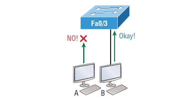
Figure 5
As you can see, port Fa0/3 is configured to allow only specific MAC addresses to communicate with this port. Hence, in the above example, host A is not permitted to access the port, but host B is allowed to communicate with the port.
Using the port security technique, you can dynamically limit the number of MAC addresses that can bind to a specific port or set static MAC addresses. This technique is mainly used in organizations where employees do not follow security policies and connect personal devices to the corporate network. In such a situation, if the user violates the security policy, it is possible to shut down the port; now, the user must provide a convincing reason why they broke the security policy.
While the above technique improves network security, there are other things you need to do to maintain or improve network security while maintaining network performance. Network experts recommend spending considerable time on network implementation and always remembering to close unused ports or move them to a new VLAN. By default, all switch ports are enabled, so you must ensure that users cannot access unused switch ports.
There are important commands to configure port security, which are as follows:
Switch#config t
Switch(config)#int f0/1
Switch(config-if)#switchport mode access
Switch(config-if)#switchport port-security
Switch(config-if)#switchport port-security
output
aging Port-security aging commands
mac-address Secure mac address
maximum Max secure addresses
Violation: Security violation mode
<cr>
One of the essential points you should pay attention to when using switches, such as Cisco switches, is the default settings related to ports. Typically, ports on Cisco switches enter the trunk state when they detect another switch is connected to them, but you must configure the button to access the port state. If you do not do this, you will not be able to use the port security mechanism. Once the above configuration is enabled, you can use port security commands. Additionally, ensure to enable the port security feature with the switchport port-security knowledge. If you look carefully at the set of commands above, you will see that the above command can be called in four different ways.
Using the switchport port-security command, you can configure the device to take one of the following actions when a security breach occurs:
- Protect: In this mode, packets sent from source addresses unknown to the switch are ignored so that the MAC addresses are not stored in the switch table.
- Restrict: In Restrict Mode, packets with unknown source addresses are dropped, but a log is generated regarding the lessons, and an SNMP message is generated.
- Shutdown: This is the default mode. Immediately disables the interface and shuts down the port. Additionally, a log is generated, and an SNMP message is sent. In this case, a shut/no shut process must execute on the interface to use the interface again.
If you want to configure a switch port to allow one host per port and ensure that the port is shut down if this rule is violated, use the following commands:
Switch(config-if)#switchport port-security maximum 1
Switch(config-if)#switchport port-security violation shutdown
Network experts are very interested in these commands because they prevent clients from accidentally connecting to a particular switch or access point. The above method looks good, but the disadvantage is that it allows only one MAC address to access the port. Hence, if another person tries to add another host to a network segment, the switch port will immediately go into an inactive state. When this happens, you must manually connect to the switch and run Shutdown commands on it to reactivate the port. Another command that network experts use is Sticky, which is used together with the mac-address order, as in the following code snippet.
Switch(config-if)#switchport port-security mac-address sticky
Switch(config-if)#switchport port-security maximum 2
Switch(config-if)#switchport port-security violation shutdown
In general, by using Sticky, you can benefit from a robust security mechanism without explicitly entering every client’s MAC address on the network. This command shortens the switch configuration process. In the previous example, the first two MAC addresses can connect to the switch port without problems and are connected to it as static addresses and entered in the running-config. Still, when the third address tries to connect to the port, the port is immediately shut down. In Figure 6, you can see a host called the lobby, which must protect against unauthorized Ethernet cable connections.
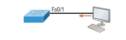
Figure 6
Based on what solution, should we ensure that only the MAC address of the lobby computer will be allowed by the Fa0/1 switch port? The solution is simple; all we have to do is add a static MAC entry based on the following set of commands:
Switch(config-if)#switchport port-security
Switch(config-if)#switchport port-security violation restrict
Switch(config-if)#switchport port-security mac-address aa.bb.cc.dd.ee.ff
To protect the PC in the lobby, we set the maximum allowed MAC addresses to 1 so that if someone tries to connect an Ethernet cable to the switch, the port will not shut down. This limitation drops unauthorized frames, but the interface and port continue to serve without problems.
Loop Avoidance
The existence of additional links between the switches is essential because in the case of failure of one link, the traffic load is transferred to the other link, and the operation of the network does not stop. However, duplicate links can cause more problems if not configured correctly. Among the most critical issues caused by double links, the following should be mentioned:
- If redundant links are implemented without proper provisioning, they will cause the switch to get stuck in an endless loop. Sometimes the said problem is called a flood storm. Figure 7 shows how a broadcast message can be continuously repeated through the transmission media in the network, quickly consuming bandwidth.
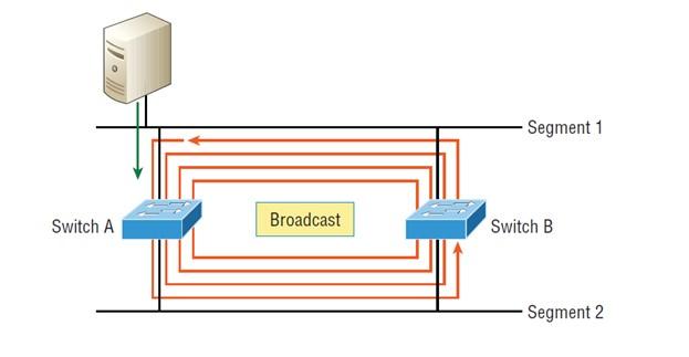
Figure 7
- A device can receive multiple copies of the same frame because that frame can enter different network segments. Figure 8 shows how the equipment can simultaneously receive an entire group of structures in other elements.
- In Figure 8, the server sends a unicast frame to router C; considering that the above structure is of unicast type, switch A sends the frame, and switch B repeats this process twice and sends the unicast frame.
- In this case, router C receives the unicast frame twice and repeats the process, which causes additional overhead in the network.
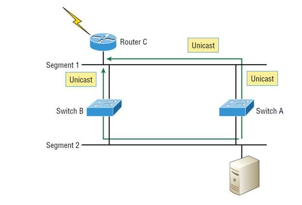
Figure 8
- As you might have guessed, the MAC address filter table gets confused about the location of the source device because the switch can receive the frame from more than one link. Worse, the controller is constantly updating the MAC filter table with various locations that point to the hardware address of the source sending the frame! This problem is called MAC table thrashing.
- Unfortunately, the above problem causes many loops in the network; worse, loops can occur in other circles. If the broadcast storm happens simultaneously, the web will not be able to perform frame-period switching!
Each of the mentioned problems will mean stopping the correct servicing of the switch, slowing down the network, and increasing the packet loss rate. Therefore, we must solve this problem somehow. To solve this problem, network experts use the spanning tree protocol, which can solve all the mentioned problems. When you implement the spanning tree protocol, you have redundant links that act intelligently and behave based on spanning tree instructions. Hence, the frames have a definite endpoint and solve the repetition problem.
FAQ
What are the core functions of a Layer 2 switch?
Three main tasks: learning MAC addresses, making forwarding or filtering decisions, and preventing loops via protocols like STP.
Why must switch ports be secured even in wired networks?
Because unauthorized devices can plug into switch ports and access the network unless port-security measures (e.g., limiting MAC addresses) are applied.
How does the “shutdown” violation mode work on switch ports?
In shutdown mode, when an unauthorized MAC address is detected, the port is immediately disabled and must be manually re-enabled.