How to Connect Two Routers in Packet Tracer Simulator — Step-by-Step Guide
Packet Tracer Simulator, more specifically, the Tracer package allows network experts to simulate equipment installation in an organization’s business environment, identify potential problems, and perform a detailed implementation. Cisco designed the above tool and is available to users for free.
These tools allow scholars to learn networking basics and improve their skills in developing Cisco technologies. One of the most fundamental problems users face when using the tool is connecting two routers in the software.
How To Connect Two Routers In Packet Tracer Simulator?
Connecting two routers and pinging between two computers on different networks is one of the most fundamental problems network engineers face.
Execution of software
The first step is to download and install the software. After installation, run the software, select the desired routers from the toolbar at the bottom of the screen, and place them on the network.
In this article, we will use 2621XM routers. Connect the two routers and then configure them to connect the devices. You can select the option you want from the other routers and place it on the screen. In this case, the routers communicate over serial links, but you can also use Gigabit Ethernet or Fast Ethernet.
The only difference between the above methods is the type of interface you use. First, we place the two routers on the screen, as shown in Figure 1. In the next step, we will add two icons representing personal computers on the network. We now intend to establish a connection between the PC-PT PC0 and the Router0 router.
To do this, click the Connections icon (on the left side of the toolbox), which resembles a power symbol, and select the Phone option in the left panel (Figure 3). Click PCPT-PC0, select FastEthernet0, and drag to Router0.
At the destination, select the FastEthernet 0/0 option (Figure 4). Repeat the same for Router1 and PC-Pt PC2. You should now have a design like Figure 5.
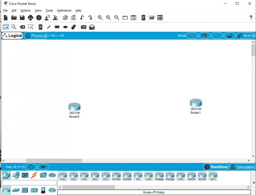
Figure 1
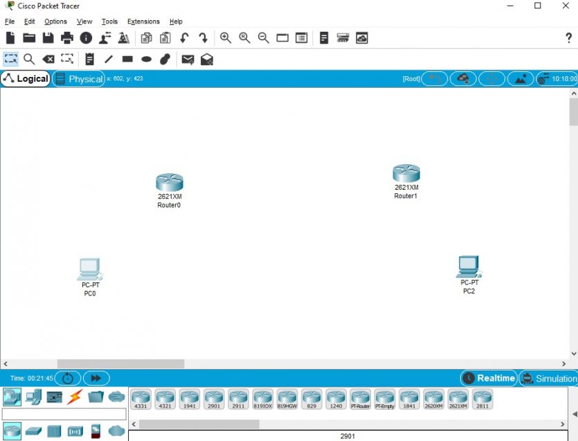
Figure 2
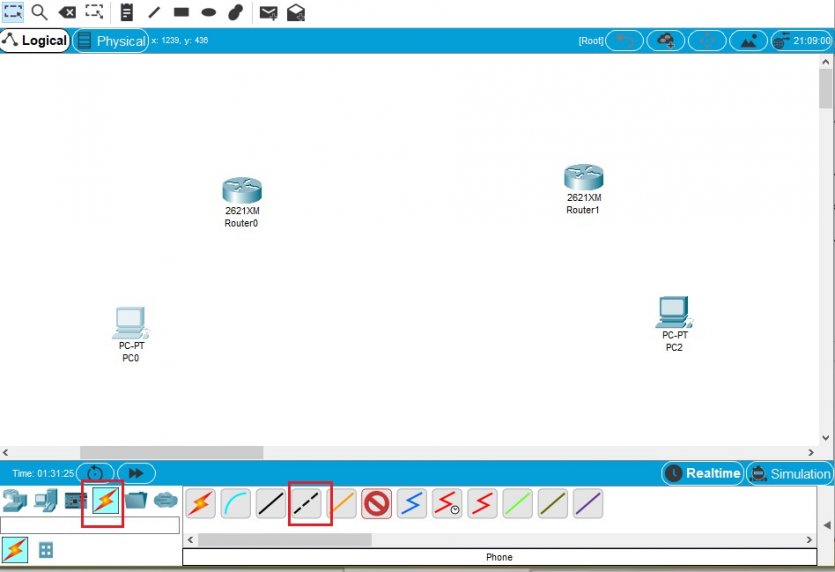
Figure 3
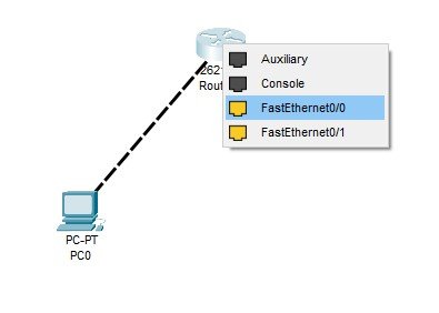
Figure 4
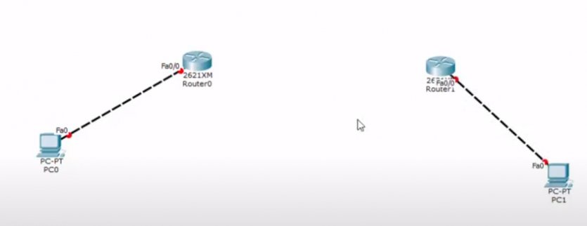
Figure 5
Now it’s time to configure the routers and connect them. To do this, use the serial DCE option or the Serial DTE option. The choice of any of these options depends on the goal you are pursuing. Of course, a third solution is less troublesome and allows you to restore the changes to the previous state in case of any mistake.
This option is called Automatically choose the connection type and allows two routers to connect. Of course, there is an additional step before doing this—Click Router to bring up the router configuration window. In the upper right of the window that appears, click on the router shutdown option to turn off the router (Figure 6).
From the left panel, select WIC-1T and drag and drop it to the physical view to add the corresponding switch to the router. After doing this, turn on the router and close the window (Figure 7). Do the same for Router1.
By doing this, access to the serial interface of the router is possible. Now, click on the Automatically choose connection type option and draw a line from Router0 to Router1 (Figure 8).
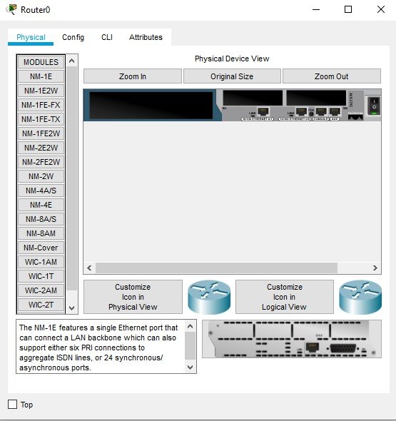
Figure 6
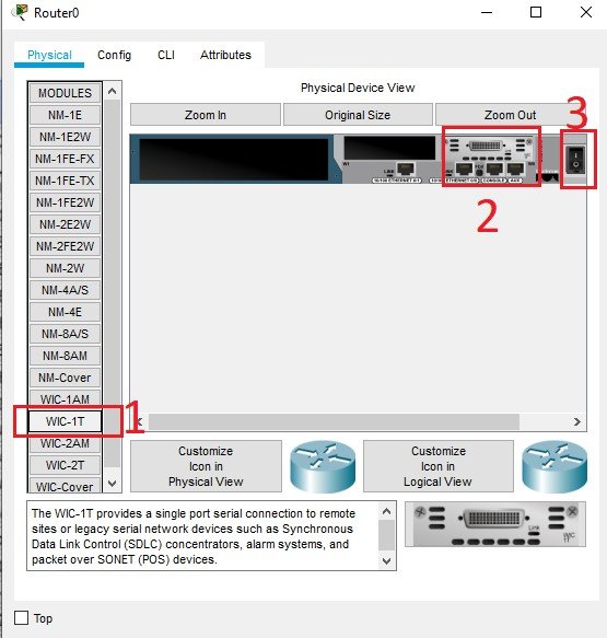
Figure 7
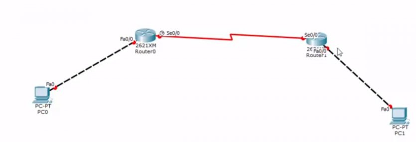
Figure 8
If you hover over the option above, you will see that the Serial option and the clock are automatically selected. Next, we need to define our network scenario. In the overhead system, we have three networks.
The first network includes the computer and the Router0 router. The second network consists of two routers, and the third network is the second computer and Router1. We now need to assign an IP address.
The IP addresses for the first network include the network itself, Fast Ethernet, and PC0, as shown in Figure 9. We repeat the same process for the second network. The second network configuration information, which includes routers R0 and R1, is shown in Figure 10.
The IP addresses of the third network, including the primary network address, the Fast Ethernet interface, and the second computer, are shown in Figure 11. Now that we have identified the lessons, we need to go to the router configuration.
Click on Router0. In the window that appears, click on the CLI tab. Type the character n, type en as enabled, and press the Enter key twice in the window that appears. The conf t command now means configuration terminal.
Type and press the Enter key. Doing so will give you access to the configuration mode (Figure 12). We now need to enter the host name. We set the hostname to R0. To do this, type the following command and press Enter.
Hostname R0
Next, we need to configure the communication ports. Type the following command and press Enter.
Int fa0 / 0
Next, we need to specify the IP address. In this step, we must enter the IP address of the first network interface (F0/0) we specified, along with the mask. The above command is as follows:
Ip add 192.168.1.1 255.255.255.0
Finally, type the command “no shut” and press Enter.
No shut
Finally, type the exit command. Now we go to the router serial configuration. Type the following command and press Enter.
Int s0 / 0
Next, we need to set the IP address as before. Type the following command and press Enter. Make sure you enter the mask address correctly.
Ip add 192.168.2.1 255.255.255.252
Run the following command to keep the router running.
No shut
Then type the exit command and press Enter. We have completed the router0 configuration, but we still have one critical parameter to set. This parameter is the clock rate. To set the above parameter, type the following command and press Enter.
Clock rate 64000
Note that the clock rate must be constant. After executing the above command, type the exit command and press the Enter key.
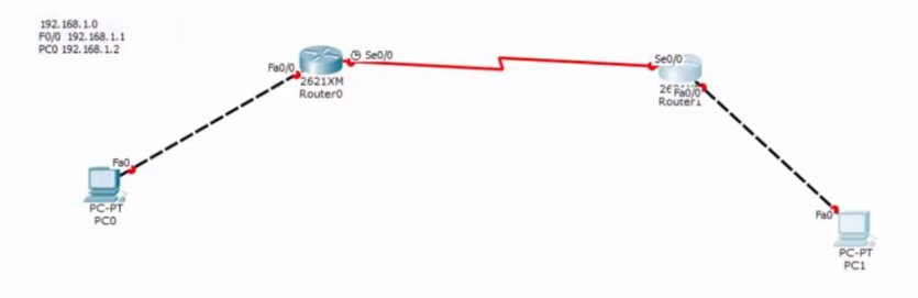
Figure 9
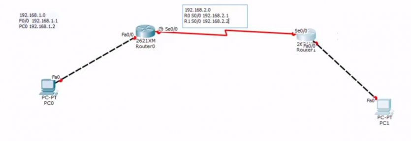
Figure 10
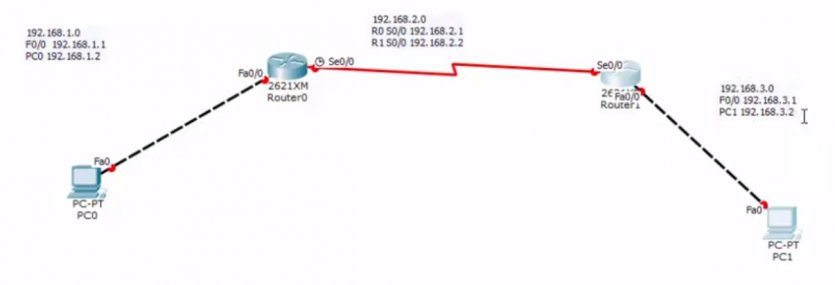
Figure 11
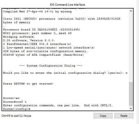
Figure 12
Router1 configuration
Next, we need to configure Router1. Click on the router above and click on the CLI tab in the window that appears. You will need to repeat all the steps you did for Router0 once more. The only difference is that you change the IP address and use the address of Router1.
If you have done everything correctly, green lights will appear around routers and computers, indicating that the equipment is active and ready to send and receive packets (Figure 13). In the next step, click on PC-PT PC0, and in the window that appears, click on the Desktop tab. On the page that appears, click on the IP configuration option.
Set the PC0 IP address to the value shown in the window that appears. In this section, we must also specify the default gateway (Figure 14). Close the above window after setting the relevant fields. Do the same for PC1.
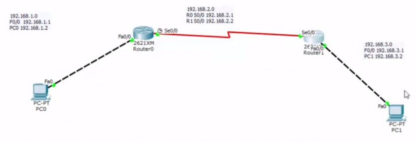
Figure 13
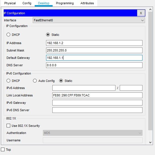
Figure 14
Ensure proper operation of equipment.
We need to ping PC0 to make sure the equipment and communications are working correctly. Click PC0 and select the Command Prompt option. Enter the following commands now.
Ping 192.168.3.2
…….
Pinging 192.168.3.2 with 32 bytes of data:
Reply from 192.168.1.1: Destination host unreachable.
Reply from 192.168.1.1: Destination host unreachable.
Reply from 192.168.1.1: Destination host unreachable.
As you can see, we received an error message when accessing the second computer, which indicates that we need to do something else. See the window above. The ping output shows that we do not yet know how to get from one router to another. That’s why we need to do a process called IP Routing.
To set the IP address, click Router0, and in the CLI window, enter the IP route command with the router interface address 192.168.3.0, the subnet mask address, and the serial port address, which is 192.168.2.2, and press the Enter key. The syntax of the above command is as follows:
R0 (config) #ip route 192.168.3.0 255.255.255.0 192.168.2.2
Now we need to do the same for Router1. Note that the serial interface address is different from the previous state.
R1 (config) #ip route 192.168.1.0 255.255.255.0 192.168.2.1
Now that the static routing process for both routers is complete and both routers can find each other, we ping PC0 again to check the result. As you can see in Figure 15, the ping was done correctly and showed that the two routers successfully connected. If we repeat the same process on the PC2 computer, the ping will work without any problem.
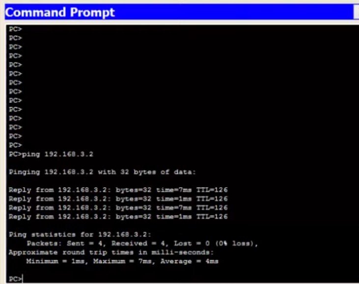
Figure 15
Last word
This article examined how to connect two routers through a serial connection and connect two devices located on different networks.
If you plan to use gigabit or fast Ethernet, the steps are similar to the above, except that you have to configure the communication ports correctly.