What Is Spine-and-Leaf VXLAN BGP EVPN Fabric — And How It Works
The Topology Of Traditional Campus Design Has Reached The Limits Of Scalability And Performance Requirements Of Today’s Network Architecture. One of the applied technologies to solve this problem is spine-end-leaf VXLAN BGP EVPN Fabric Architecture.
Spine-And-Leaf Topology: The above technology provides a strong backbone network that meets the demand for high-density and multi-gigabit traffic. The approach allows simultaneous access to high-performance databases, playback of 4K-resolution media content, and transfer of terabytes of files without delay or slowdown if thousands of users are accessing simultaneously.
Column and leaf architecture (a highly unusual name for a technology concept in the IT industry) addresses scalability and functional demands in academic networks through a simple architectural approach. To understand column and leaf architecture in today’s network design concepts, we need basic information about its components. VXLAN BGP EVPN encapsulates layer 2 in layer three frames and, for this purpose, uses the L2VPN EVPN address family ID (AFI) in the BGP protocol.
The spine-and-leaf architecture can run various programs and is not limited to VXLAN. Another use of column and leaf architecture is the Cisco-based application infrastructure COOP (Council of Oracle Protocol), which uses VXLAN instead of VXLAN to perform endpoint mapping (IP) and location announcement.
The architecture of the Spine-And-Leaf
Symmetric architecture is predictable. You can visualize a traffic pattern in a spine-and-leaf architecture. The connection is leaves – spine – leaves.
The traffic flow starts from the source leaf, which directs it towards the spine. Then, the spine leads it toward the destination leaf. Each source endpoint (any device, server, workstation, etc.) is just two jumps away from its destination. The figure below shows this topic.
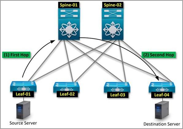
- First jump: Source leaves up the spine
- Second jump: Spine up goes to the destination
Layers of spine and leaves
There are two layers in a single spine-and-leaf topology.
The spine layer is the junction of the leaves. Spins (spines) reflect all the routing information to their clients (in this case, the leaves). The spine layer configures BGP EVPN to act as a reflector in the path. You designate them as meeting points for the underlying multiplayer traffic in the spine layer. Here, the spine layer is considered a distribution layer or an aggregation in a three-layer scheme, but more work is done than simply aggregating layer two components.
The leaf layer provides all endpoints of access to Fabric and makes network routing decisions. All layer leaves have three cores. In the three-layer design, the core layer makes all the routing decisions. The core is usually active hardware in a three-tiered architecture, and additional centers are configured as standby nodes using FHRP (first-hop redundancy protocol). Of course, be careful that this is not true of the leaf in VXLAN BGP EVPN.
One of the most powerful features of VXLAN BGP EVPN is the anycast gateway, which allows the leaf layer to act as a sizable active core switch. Each leaf can drive traffic to its destination. You are not limited to a 3-core active layer here. In fabric-based, locally developed virtual networks, each leaf is an active core that delivers remarkable performance and scalability tailored to today’s data center networks.
Redundancy in spinal and leaf topology
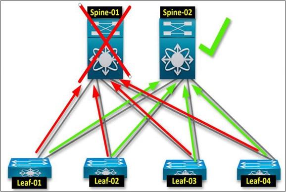
Like all manufacturing environments, redundancy is essential. To comply with redundancy requirements, a fabric component must have at least two reels.
This rule is also present in the architecture of the spine and leaves. All leaves are connected to all spins. Here, at least one graft goes from one leaf to the spine. The following figure shows a resonance of the coping with failure scenario in a four-leaf/two-column topology.
Redundancy leaves
Now, getting information about redundancy in the leaf layer is better. The redundancy aspect differs slightly from the spine layer since a leaf connects all the network’s endpoints, access switches, servers, etc.
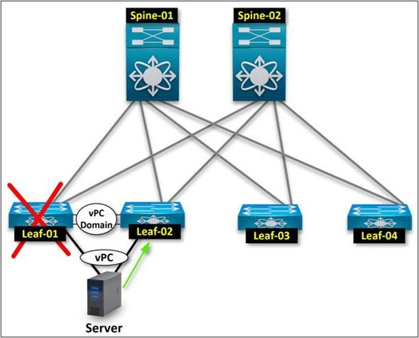
To clarify the discussion, it is best to review vPC on the Cisco Nexus platform briefly. vPC provides the required leaf redundancy by combining two independent leaves in a vPC amplitude.
Let’s assume you have a server with dual NICs. Since the leaf layer is where you connect all your end devices, access switches, and servers to the Fabric, redundancy to the end device, in this case, the server, is considered.
The above approach is achieved by configuring the end host PC. The leaf layer provides redundancy to the server. If you lose leaf-01, Leaf-02 should continue the server connection mechanism to keep the network functioning.
Network Infrastructure
When I first started learning VXLAN, it took me a while to focus on underlay and overlay. Explaining this to my colleagues and clients was also a challenge. Luckily, I learned the perfect simile to describe it.
Let’s compare the VXLAN infrastructure to rollers. The air train has rails, engines, and brakes, which are infrastructure. Roller substrates are vital components that host and serve the built-in.
No, let’s compare it with VXLAN. In the VXLAN infrastructure, physical links between leaves and spins (rails) are connected to allow customer traffic (roller cars and riders) to move on the Fabric and reach their destination.
An essential aspect of infrastructure is equal-cost multipath (ECMP) routing in the links between leaves and switches. ECMP uses leaf-to-column active links for traffic flow. The above approach is somewhat similar to link aggregation in L2, but you do it based on the L3 architecture.

Coverage Network
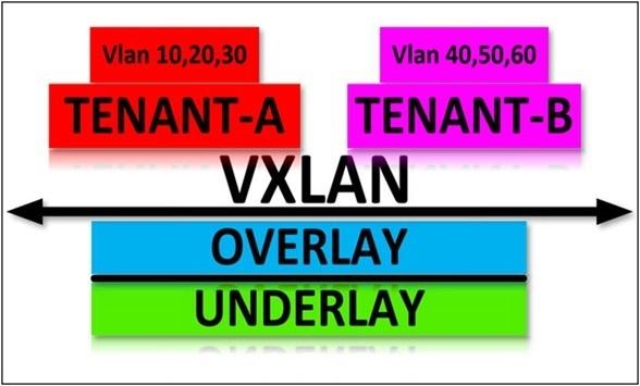
A cover (cars and trans riders) is where VXLAN’s advantage over traditional networks shows. VXLAN offers a downtime tackle feature, especially in conjunction with multi-tenant-based architectures. Using the multi-tenant model, you can run different client networks utilizing a fabric.
The tenant refers to a virtual grid inside the same VXLAN fabric, one of the main advantages of software-defined networks (SDN) or software-driven networks.
Compared to the air train, the tenants are air-to-air vehicles. Each car (tenant) carries a group of passengers (let’s connect passengers to VLANs), and only passengers (VLAN) inside the exact vehicle (tenant) can talk to each other.
Here, I mentioned ECMP and how to use each leaf’s links to different columns. ECMP provides the advantage of simultaneously using two rails (the connection between leaves and spins) for the trolling machine (tenant).
Air train cars (tenants) can move faster on two rails (links). If a fence (link) breaks down, the car still has another rail to continue on the track. The figure below shows this topic.
Traffic flow of the spine and leaves
Now that we have a clearer picture of the VXLAN fabric components, we need to see how the Fabric works and what VXLAN needs to communicate in the infrastructure.
Broadcast Unknown Unicast and Multicast (BUM Traffic)
Since the L2 frames in VXLAN are enclosed in L3, you stop the playback mechanism at the fabric level. All broadcasting means that a network gets information about its connected devices, but how does VXLAN get that information when the all-broadcast model has stopped playing?
Here, a multiplayer approach is used. BUM traffic uses three messaging mechanisms to communicate on a network: broadcast, unicast, and multicast. Multicast is an alternative to all playback that can use L3 to publish information.
Underlay Multicast
Now that you know that multicast replaces the all-playback model, you should also know that the multicast architecture should be implemented in the underlying layer. How is this process done? You specify a multilayer prefix to map multiplay groups to ID (VNI) in an extended virtual local network.
There is a multiplayer group in each VNI. Multiplayer messages are sent to an appointment point, which you usually assign to columns.
Sublayer Routing
Subsurance routing in VXLAN is essential for fabric manufacturing. A dynamic routing protocol, such as OSPF or IS-IS, is designated as the Internal Gateway Protocol (IGP) to establish a neighbor-to-neighbor process across all leaf-to-spine physical links.
Once the above mechanism is activated by implementing BGP over OSPF or IS-IS, the BGP EVPN becomes significant, realized, and operational. You create a Loopback address on each switch (spin and sheet) and add its information to OSPF, using it as the same address as BGP. How do you do this? Pay attention carefully.
The first step is to enable OSPF or IS-IS on leaf-to-spine links, configure a loopback interface on each device, and provide the OSPF information required by the IGP protocol.
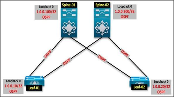
The next step is to use the back loop interface to match the BGP at the top of the OSPF by placing the underlying routing. Leaf-01 has two valid paths to spins, and then the BGP between them is checked using a back loop.
Here, the operations are carried out as follows:
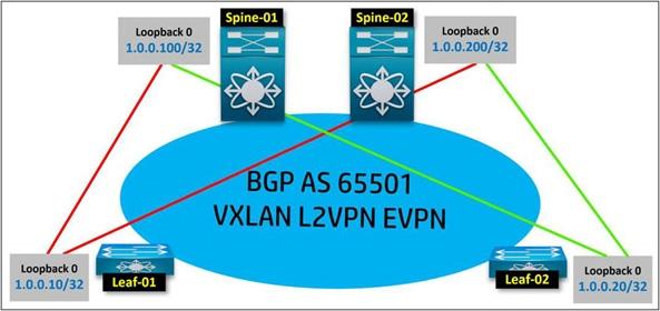
BGP Neighbors Leaf-01 Spine-01
1.0.0.10 1.0.0.100
BGP Neighbors Leaf-01 Spine-02
1.0.0.10 1.0.0.200
BGP Neighbors Leaf-02 Spine-01
1.0.0.20 1.0.0.100
BGP Neighbors Leaf-02 Spine-02
1.0.0.20 1.0.0.200
A connection is established between the devices after accessing the back-loop interfaces for BGP and peer-to-peer. Once you’ve done this, BGP peer-to-peer, you’ve prepared the BGP infrastructure necessary to send traffic with VXLAN EVPN.
Overlapping routing
You’ll need a basic configuration to allow a tray to move between the machines. In the VXLAN term, you have to prepare everything from the VXLAN infrastructure to the fabric tenants, the top of which are called constructions.
For this reason, VXLAN must run an overlapping path through a mechanism. We create the EVPN neighborhood between the leaves, so why not do it for the spine? The spine does not resize L2 frames from/inside VXLAN. Spins work to aggregate and act as reflectors of the BGP pathway.
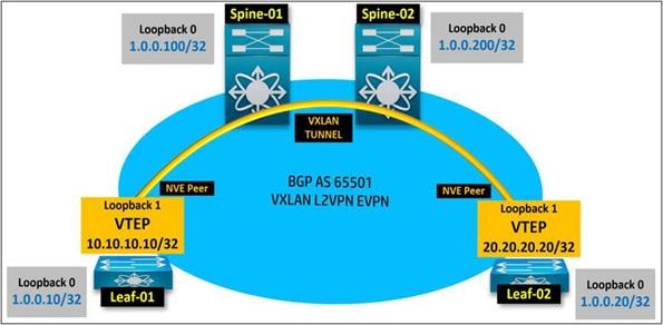
You create a virtual network interface (NVE) and use it to encapsulate L2 frames. VXLAN uses the source back loop interface dedicated to NVE to create a VXLAN tunnel between the leaves.
Note that the back loop assigned to NVE is not the same as that used to match the BGP. You can use it better, but it’s best to have a specific loopback for VXLAN NVE purposes.
All client traffic must pass through the tunnel when it reaches the Fabric through each leaf. Thus, traffic is passed between the leaves and through the tunnel using the EVPN fabric.
Of course, as mentioned, spins are not visible as a tracking mechanism and only see the leaf gate for the origin and destination. The figure below shows that LoopBack 0 is the peer-back loop interface for BGP EVPN. Here, you can create another loopback to get VXLAN tunnels between the leaves.
Let’s select Loopback 1 as NVE Loopback. When we do this, we can effectively align NVEs. The interface address loopback 1 is the endpoint of the VTEP virtual tunnel, also called the Virtual Tunnel End Point.
FAQ
What is “spine-and-leaf” topology?
It’s a two-layer physical network: “leaf” switches connect to servers/devices; “spine” switches inter-connect all leaves — any leaf-to-leaf traffic goes via spine, ensuring predictable latency and non-blocking bandwidth.
What do VXLAN + BGP EVPN add on top of that?
VXLAN encapsulates Layer-2 frames inside Layer-3 packets so Layer-2 segments (VLANs) can stretch over the fabric. BGP EVPN acts as the control plane, distributing MAC and IP reachability across leaf (VTEP) devices without flood-and-learn, enabling multi-tenancy, overlay scalability, and efficient host mobility.
Why is this design preferred for modern data centers?
Because you can scale simply by adding leaves (more servers) or spines (more bandwidth) — the network remains predictable, provides equal-cost multipath (ECMP) for load balancing, supports isolated tenant networks (virtual overlays), and reduces broadcast/flooding overhead compared to classic VLAN-based designs.