
CCNA Training: Introducing SPAN (Switched Port Analyzer) for Network Monitoring
SPAN (Remote Switched Port Analyzer) or RSPAN May Be Used Under Different Names in Other Brands, such as 3COM Switches, where it is known as Roving Analysis Port (RAP).
SPAN: To briefly introduce the Port Mirroring technique, it sends a copy of network traffic, including an entire LAN, to one or more devices and ports to monitor the network accurately.
Of course, this method does not require you to worry about your information security because, by activating it, you only receive the Metadata package you need for the monitoring software to retrieve and display the desired information.
Using the Port Mirroring technique, you can detect security vulnerabilities, network issues, and other problems. You can also mirror all inbound traffic (ingress) and outbound traffic (egress) on a single port, or all interfaces and VLANs of a switch, for monitoring. This is usually used more commonly for incoming network traffic.

What is SPAN?
Property (Switch Port Analyzer (SPAN, sometimes called Port Monitoring) and Port Mirroring also call for analyzing network traffic utilizing analyzers. Tools: Network analyzers can provide a Cisco (Cisco Switchprobe) probe, a Remote Monitoring Probe tool, or software. The most straightforward network analysis software is Wireshark or Microsoft Network Monitor, which is called Sniffer network probe tools.
What is SPAN, and why do we need it?
The SPAN property is generated for the switches, as there is a fundamental difference in performance between the switch and the hub.
There is no need for SPAN in the hub. If the data packet reaches one of the hub ports, that packet is copied and sent to all ports except the primary port.
However, after turning it on in the switch, the layer two tables are created from the MAC Address or physical source address (Source MAC Address) of the sent packets. After making this table, the switch sends the packets directly to the destination port based on this table.
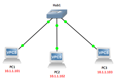
The following figure shows how a hub transfers a packet from source to destination.
As it turns out, the hub copies or sends the input packet to one port over the other ports, so you can easily eavesdrop on the entire network traffic by setting a sniffer.
We ping PC1 from PC2 and confirm we can easily download the package.

Ping
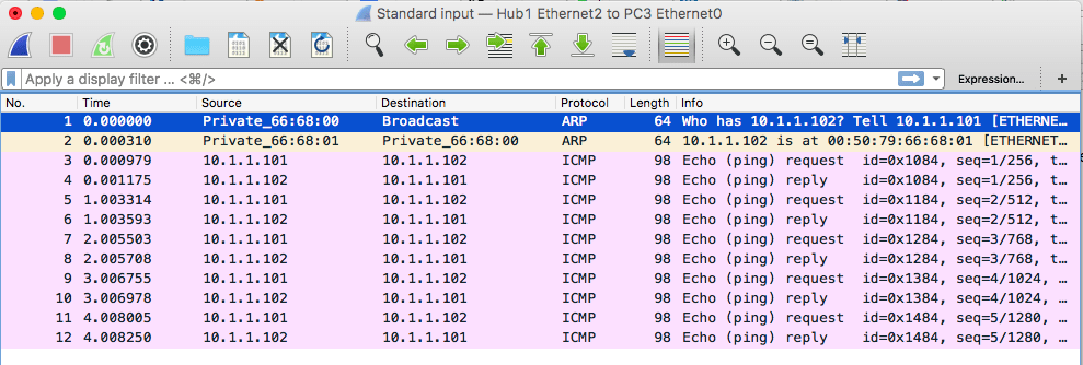
Wireshark capture
However, as shown in the figure below, the switch understands computer two’s physical address and keeps it in its MAC table.
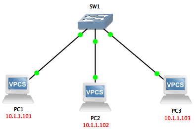
As soon as the data packet is sent from computer 1 to computer 2, the switch uses the MAC table to forward the packet directly to the port connected to computer 2. Therefore, sniffers and monitoring systems cannot access traffic within the network.
This type of traffic sent to a specific destination is called Unicast.
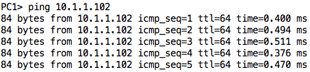
Ping again
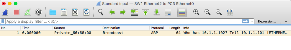
Wireshark ARP request
But in the example above, the following types of traffic can be received and analyzed by sniffer and monitoring systems:
- Broadcast traffic
- Multicast traffic
- Unknown monopoly traffic
Send traffic on the switch, usually.
Send traffic to the Port Mirroring activation time switch
As mentioned, the traffic switch only sends traffic to the destination you must send it to.
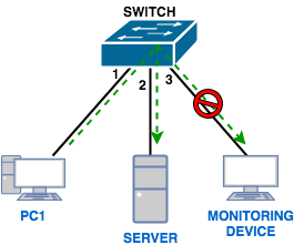
An additional feature is needed in the switch to access Unicast packages: the SPAN property. As shown below, with this feature, the traffic between the two ports in the stream can be copied to another port, called SPAN, to be used by Sniffer and the monitoring system.
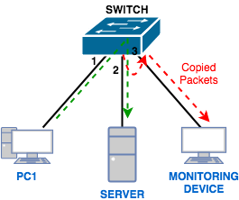
Switched Port Analyzer (SPAN)
0The capabilities of defining a destination in the SPAN technique have greatly improved since the day this technique was introduced. When we talk about SPAN, the source and destination addresses are on the same switch to which we are currently connected.
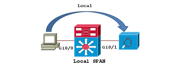
Local SPAN
The rules for RSPAN Source are similar to those for SPAN Source, meaning that the source must have at least one physical port or a VLAN on the switch.
The main difference between RSPAN and SPAN is the destination, which in RSPAN no longer requires a port on the same switch but can be defined on another switch.
In such a case, we create a dedicated VLAN called RSPAN VLAN to implement RSPAN; this VLAN includes the ports defined in the source switch and the destination switch. As you can see in the image below, the traffic sent from the RSPAN VLAN as a trunk will be visible at the destination.
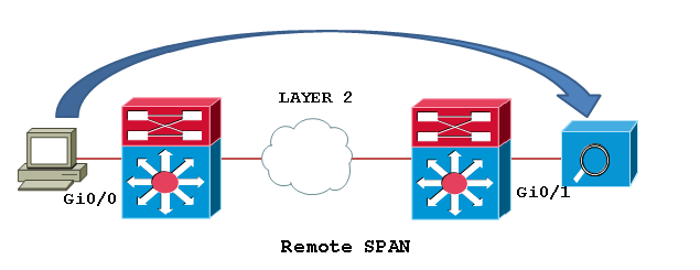
Remote SPAN – RSPAN
Finally, if our traffic is to pass through several different routers and network infrastructures, we use another technique called Encapsulated Remote SPAN or ERSPAN.
The source defined in SPAN consists of at least one physical port or VLAN on the same switch that we want to monitor. The destination port must also be on the same switch. Once configured, SPAN Source traffic is sent to the SPAN Destination Port.
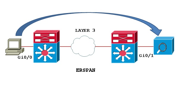
Encapsulated Remote SPAN or ERSPAN
SPAN startup requirements
SPAN, RSPAN, and ERSPAN all have a series of technical conditions and requirements to be able to monitor and send traffic properly:
- SPAN Source can be a physical port or a VLAN; the two can not be combined.
- A-SPAN Source Port cannot be a Destination Port simultaneously, and vice versa.
- Whether SPAN, RSPAN, or ERSPAN, each session can mirror traffic to only one destination, and sharing on destination ports is meaningless.
- When Trunk ports are defined as Sources in SPAN, all traffic in VLANs is monitored by default. If you want to monitor only specific traffic, you must filter your desired VLAN.
Catalyst Switches that support SPAN, RSPAN, and ERSPAN:
| SPAN Support | RSPAN Support | ERSPAN Support | Catalyst Switches |
| Yes | No | No | Catalyst Express 500/520 Series |
| Yes | Yes | Supervisor 2T with PFC4, Supervisor 720 with PFC3B or PFC3BXL running Cisco IOS Software Release 12.2 (18) SXE or later. Supervisor 720 with PFC3A that has hardware version 3.2 or later and running Cisco IOS Software Release 12.2 (18) SXE or later | Catalyst 6500/6000 Series |
| Yes | No | No | Catalyst 5500/5000 Series |
| Yes | Yes | No | Catalyst 4900 Series |
| Yes | Yes | No | Catalyst 4500/4000 Series (includes 4912G) |
| Yes | Yes | No | Catalyst 3750 Metro Series |
| Yes | Yes | No | Catalyst 3750 / 3750E / 3750X Series |
| Yes | Yes | No | Catalyst 3560 / 3560E / 3650X Series |
| Yes | Yes | No | Catalyst 3550 Series |
| Yes | No | No | Catalyst 3500 XL Series |
| Yes | Yes | No | Catalyst 2970 Series |
| Yes | Yes | No | Catalyst 2960 Series |
| Yes | Yes | No | Catalyst 2955 Series |
| Yes | Yes | No | Catalyst 2950 Series |
| Yes | No | No | Catalyst 2940 Series |
| No | No | No | Catalyst 2948G-L3 |
| Yes | Yes | No | Catalyst 2948G-L2, 2948G-GE-TX, 2980G-A |
| Yes | No | No | Catalyst 2900XL Series |
| Yes | No | No | Catalyst 1900 Series |
Implementing SPAN at Cisco
Consider the following network: PC2, PC3, and PC4. It is a good idea to send a copy to PC5 for any traffic they send and receive. S, we have to introduce the GIG 0/3 interface as SPAN.
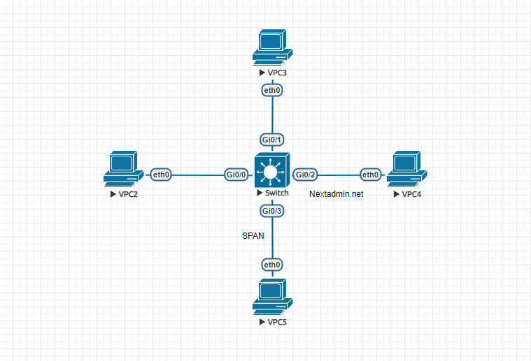
Specify the following command to specify sources:
Switch (config) # monitor session 1 source interface fastEthernet0 / 0 – 2 bath
Note: To send traffic send and receive both, and for traffic send tx and traffic receive rx, if we do not enter anything, both will be activated automatically.
And now, to send a copy of the traffic to PC5, we enter the following command:
Switch (config) # monitor session 1 destination interface gigabitethernet0 / 3
FAQ
What is SPAN in Cisco networking?
SPAN (Switched Port Analyzer) copies traffic from one or more source ports or VLANs to a destination port for monitoring and analysis.
Why is SPAN used in network monitoring?
SPAN allows administrators to capture and analyze network traffic that would otherwise be switched directly to its destination, enabling troubleshooting and security analysis.
What is the difference between SPAN and RSPAN?
SPAN mirrors traffic on the same switch, while RSPAN can send mirrored traffic across switches using a dedicated VLAN.