Familiarity With The Network Architecture Of Organizational Data Centers And How To Deploy Their Components
Communication Networks Play An Important Role In The Success Or Failure Of Large Organizations.
Network Architecture protects organizations from all kinds of risks, especially security risks, which is considered to guarantee their survival.
Understanding the structure of data networks helps us better understand network vulnerabilities and focus on areas vulnerable to cyber-attacks.
In communication networks, network architecture refers to how organizational networks in a building or adjacent buildings are connected. Information is transmitted on the web without the slightest delay and error.
This article will teach us how to implement enterprise networks and data centers.
Understanding network architecture helps us understand network vulnerabilities, as hackers always look for ways to infiltrate corporate networks and steal or manipulate information. When a hacker succeeds in entering an enterprise network, they will gain the ability to track information that is being transmitted over the web or steal valuable information. To solve this problem, you need to understand the structure of the network and the data that flows through it.
A typical network consists of the following three main parts:
- A data center network hosts the organization’s servers and applications.
- The leading network is the highway that connects all parts of the network, including the user network, data centers, remote networks (branches of an organization) to each other, and finally to the Internet.
- The user network is a subset of the leading web and is responsible for connecting users to each other. The user network is usually based on distribution and access networks. Figure 1 shows the architecture of a typical organizational network.
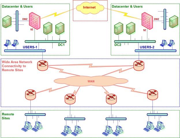
figure 1
In the upper left corner of Figure 1, we see the primary data center called DC-1. The user network is also located on the data center site under Users-1. In the upper right corner, we see a secondary data center called DC-2, consisting of a network of users on the secondary data center site. Two data centers are connected to the Internet through two firewalls located in two data centers. In the center of the chart, we see a WAN, which includes routers related to the Service Provider (SP) network, which is responsible for connecting local area networks and the Internet. At the bottom of the chart, remote sites (branches) link to the organization’s core network through a service provider network.
The central network, user, and data center
As mentioned, an enterprise data network consists of small and large networks managed through a central network. The leading network is the backbone that connects users to the data center, remote offices, and the Internet. For example, data centers host the networks on which organizations’ servers are located. Some organizations use two data centers to maintain the principle of high availability and high availability. If one data center fails, another can replace it in whole or part. One thing to keep in mind when designing user networks is the number of organizational users outside the organization (telecommuters), the geographical area, and the number of branches of an organization. Distribution switches are installed in central campus locations, and access switches are installed in buildings and small spaces.
- For example, in Figure 2, we have the architecture of an organizational network that hosts two data centers at the data center layer. These data centers do two essential things; The first is that they serve the central layer, and the second is that whenever one encounters a problem, the other assumes the functions of the data center out of the circuit.
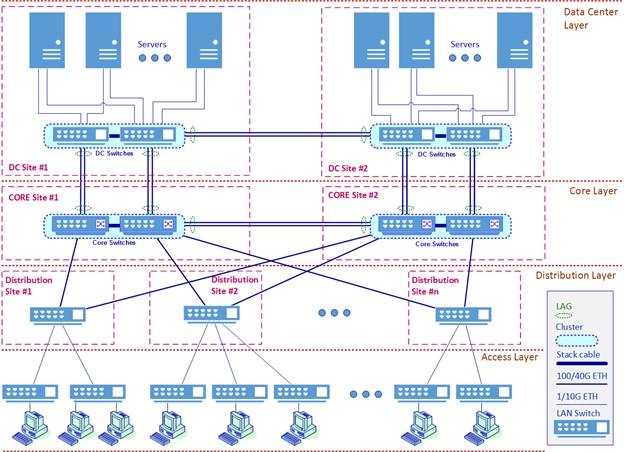
figure 2
An important point to keep in mind when implementing such networks is to choose the right equipment, such as switches, responsible for managing traffic and workloads. In general, core switches have more reliability, better features, and capability than distribution switches; therefore, good routing capabilities and preparation of an optimal and stable transmission structure.
Packages provide. Distribution switches must have a large switching capacity to process the traffic from the access switch. For this reason, it is better to use central controls in the Core layer (major network) and distribution switches in the Distribution layer. Because the access switch is connected to network equipment and users, it must have many ports. Enterprise network architecture depends.
In Figure 2, the data center switches are located at the top and are connected to each server via two cables. These connections have a dual purpose; The first is to ensure that the redundancy principle is achieved so that if one of the cables and transmission channels fails, the other manages the transmission process. Second, they can link aggregation to make more switching capacity available. Also, communication channels can be on a fiber or copper substrate.
In the middle of the image, we have the central switches.
As the name implies, these switches are at the heart of the enterprise network. They are responsible for communicating between the user network and the data center and allow remote sites, the Internet, and other networks to share with the corporate network. The connection between the central switches and the data center switches can be implemented in Layer 2 or 3, with or without overlapping technologies.
The user network is located in the distribution and access area. The access layer hosts switches that connect users to the enterprise network, while the distribution layer integrates access switches. For example, in a campus network, a distribution switch is installed for each building or group of buildings, and access switches are connected to the distribution switch. Distribution switches are usually installed following the redundancy principle; two controllers are installed on each side, and both switches are connected to the network.
Layer 2 switching topology and Layer 3 routing
Layer 2 switches are devices that switch packets between ports, while Layer 3 switches or routers look at the packet Layer 3 header and perform routing. The process for doing this is shown in Figure 3. Here, D stands for the destination address, S stands for the source address, and D and S are for L2 and L3, respectively.
At the top left of the image, we see a LAN switch receiving a frame. The switch then looks at the MAC address of the destination, decides whether to transfer the packet and sends the frame to the destination port, port 3.
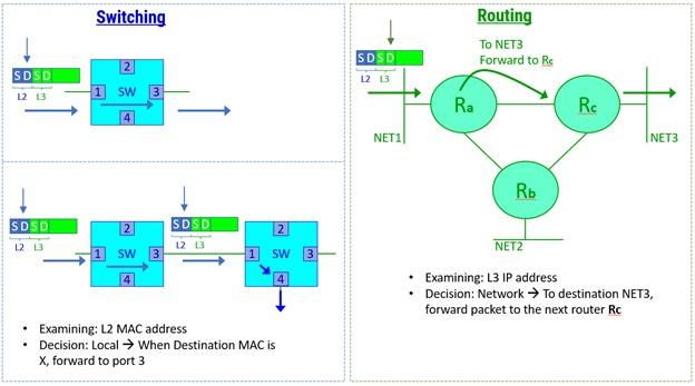
Figure 3
At the bottom left, we see how a frame passes through the network of switches. The frame enters the button on the left, which sends the packet to port 3. Port 3 connects to port one on the right switch, which looks at its MAC address and forwards the box to the right button, port 4. Decisions about how to send frames are made locally. That is, the decision is made without interacting with other controls so that no additional load enters the network.
The routing process is performed in layer 3, shown to the right of Figure 3. When a packet enters the router, the router looks at the Layer 3 destination address and checks to see if the packet destination is valid in the routing table, then performs the routing process and sends the packet to the next hop.
We generally use Layer 2 switches to connect users to the network. We use Layer 3 buttons at higher levels, the distribution level, the core, or the data center, to divide the network into smaller networks (subnets).
Then In Figure 4, we see a standard router on the left and a Layer 3 switch on the right. And In a regular router, devices such as personal computers or Layer 2 switches are connected.
In Layer 3 switches, the hardware and software requirements we need to send and receive data packets are provided as a single product. Layer 3 interfaces (called VLAN interfaces in Cisco equipment) are software interfaces configured on the switch. Here, virtual local area networks (VLANs) are configured, an L3 interface is assigned to each, and external equipment is connected to the switch’s physical ports.
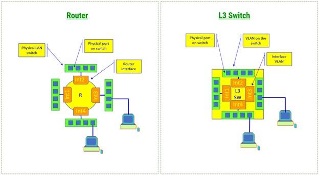
Figure 4
Virtual LANs and network splitting into different subnets have many advantages. They give us more design flexibility, as each section can have an IP subnet with permissions and access rights to its servers. It is possible to implement routing protocols. , Clients receive broadcast messages only on their subnets, and any cyber attack only affects that subnet. These are just some of the benefits of networking.
L2 and L3 architecture
One of the significant challenges that network designers and architects face is choosing the architecture on which the enterprise network is to be implemented. One thing to keep in mind about Layer 3 architecture is that Layer 3 can be implemented anywhere in the network. When Layer 3 is implemented in the main switches, their IP addresses will be the default gateways for users. When layer three is implemented in data center switches, their address will be the default gateways of the servers. The two most widely used topologies used by network experts when implementing enterprise networks are shown in Figure 5. To the left of Figure 5, we have the following settings:
Virtual Local Area Networks (VLANs) Configured on Main Switches: Here, VLAN 50 and VLAN 60 are users of local area networks. Each user has a virtual LAN, multiple physical ports, a logical L3 interface, and a VLAN interface (if using Cisco equipment). In the example above, the VLAN50 IP address is 10.50.1.1/16, while the VLAN60 IP address is 10.60.1.1/16.
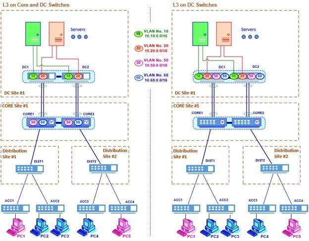
Figure 5
Virtual LANs are configured on data center switches.
VLAN 10 and VLAN 20 are virtual server LANs. Each virtual LAN server has several physical ports and an L3 logical interface, or LAN interface. For example, the IP address of the VLAN 10 virtual network interface is equal to 10 10.10.1.1/16, while the IP address of the VLAN 20 virtual local network interface is equal to 10.10.1.1/16.
The default user gateways on 10.50.0.0/16 and 10.60.0.0/16 networks are 10.50.1.1 and 10.60.1.1, respectively.
On the right, we see a different topology, where the interfaces of all virtual LANs are located on the data center switches. In the topology on the right, we have the following configuration:
- All VLANs are configured on data center switches.
- The main switches are used as Layer 2 devices. The default gateways for user devices and servers are on data center switches.
Data flow in L2 and L3 architecture.
Just as Layer 2 and Layer 3 architectures are different, so are data flows in these architectures. To better understand this issue, pay attention to Figure 6. In the topology on the left, we have the following configuration:
- When sending packets from users to servers, users in VLAN 50
- When sending packages, VLAN 10 or VLAN 20 servers send packets to the default gateway 10.10.1.1 with the center-left button. The packets are then routed to the L3 interface on the left core switch and the user. Or VLAN 60 sends packets to the default gateway, the L3 interface on the core switch, and from this point, the boxes are routed to the L3 interface of the center switch and the server (left switch). Pay attention to the numbers in the image to better understand sending and receiving information.
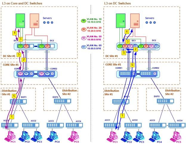
Figure 6
In the topology on the right, we have the following configuration:
- Data center switches are the default gateways for users and servers, so packets from both are sent to data center switches, and the routing process is done internally.
Data flow in L2 and L3 architecture is based on the redundancy principle
Now let’s look at how packets are transmitted over the network. Here we assume that the L3 user interfaces are on the central switches. In Figure 7, a computer with the address 10.60.10.10/16 sends information to a server with the address 10.20.1.100/16.
In an enterprise network, under normal conditions, when all network components are working smoothly, the data transfer flow is as follows:
- When PC2 sends packets to a server, the packages are delivered to the default gateway, the central switch 10.60.1.1 (1).
- From switch 10.60.1.1, packets are sent to the central switch at 10.20.1.1 (2).
- The packets are then sent to server S1 at 10.20.1.1 (3).
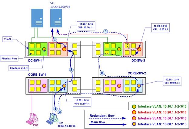
Figure 7
When something like a malfunction occurs, for example, the DC switch on the left side of the image called DC-SW-1 fails, the following happens:
- In this case, server S1 selects the DC vh switch to the right, called DC-SW-2. Then the packets from PC2 to the server are sent to the correct core switch (a).
- The core switch on the right directs the packets to the next-hop (b), which is the DC switch on the request (DC-SW-2) to send the DC switch on the right of the packets to the server (c).
last word
As you can see, the design considerations of a data network are very detailed, so each design must be tailored to the needs of an organization. Note, however, that unless you have a good understanding of the structure of a network, you will not be able to implement an integrated network with the best performance and a high threshold for failure.