


How Wireless Power Transmission Technology Supplies The Energy Needed By The Devices
If You Are An Organized And Precise Person, You Will Still See A Lot Of Electrical Cables In The Corners Of Your House That Are Tied Together And Have A Lot Of Dirt Sitting On Them.
Also, sometimes you have to unsightly connect a special cord to the outlet in hopes of plugging in the chargers for your various devices with short lines.
Although these tangled wires make people’s lives easier, they can make for an unsightly sight.
For this reason, various wireless chargers with unique technologies have entered the world of technology to save you from this problem and ever wondered how a wireless charger works?
The efforts of scientists to achieve wireless energy transfer technology
While wireless energy transfer technology may seem futuristic, the reality is something else. In the late 1800s, Nikola Tesla proposed theories on wireless energy transmission, one of his most spectacular demonstrations being remote electrification (artificial lighting with the ability to discharge millions of volts) in his laboratory in Colorado Springs. Although Tesla’s work was amazing then, investors and large companies did not support his plan for this unique, innovative method for various reasons.
It should not be widely operated and used. Since then, researchers have developed various methods to transmit electricity over long distances without wires. Of course, some of them remained theoretical, but others made their way into consumer devices like electric toothbrushes that some of you may be using.
What Tesla did was amazing but didn’t quickly translate into a practical, widespread wireless distribution method. Since then, researchers have come up with many designs for transmitting electricity over long distances without the need for wires. Some remained only at the level of theory or prototype, but some were used (Figure 1).

figure 1
Radio waves are energy, and people use them daily to send and receive mobile phone, TV, radio, and Wi-Fi signals. In general, radio waves’ directions and absorbed by antennas that are tuned frequency of the waves. Of course, electric power transmission in the above method has risks and is ineffective if improperly used.
For example, electric toothbrushes that come in direct contact with water may pose a risk to people, especially when the wet toothbrush is placed in the charging compartment after use. In addition, humidity quickly causes these products’ boards and hardware components to deteriorate. This issue has caused most toothbrushes to be charged through the inductive coupling technique (Figure No. 2).
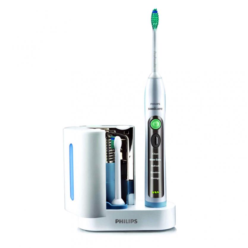
figure 2
Let’s go to the electric toothbrush to understand the operation of electricity transfer by the inductive coupling method. In general, the base and handle of an electric toothbrush include coils that allow the battery to be recharged.
This is done during the inductive coupling process, in which magnetic fields are used, which are produced naturally from the movement of the electric current in the coil. Whenever an electric current passes through a ring, a magnetic field is created in a circle around the ring. In this regard, increasing bent wires around the coil core strengthens the magnetic field. Therefore, the more coils there are the larger the magnetic field.
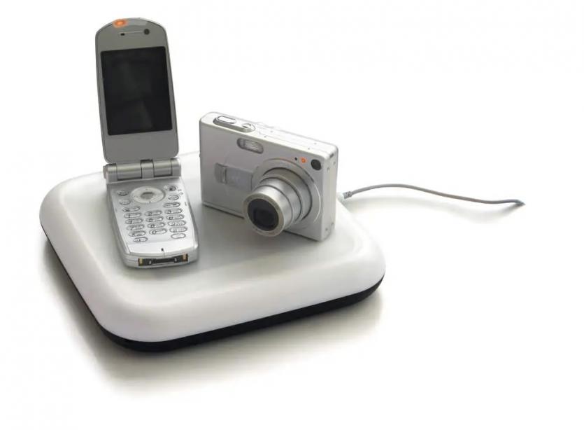
Figure 3
Electric current flows through the coil inside the charger, which creates a magnetic field in the ring. When the toothbrush is placed in the charger, the magnetic field induces a current in the second coil connected to the battery. This mechanism charges the battery of the electric toothbrush. This is the same technique that transformers work on. The same process is generally used to charge other equipment and gadgets with wireless charging technology. Of course, there are different ways to transmit electricity over longer distances, which we will mention below. This process consists of the following three main steps:
- Current flows from the outlet to the charger coil, creating a magnetic field. In the transformer, it is called the primary winding.
- When the toothbrush is placed on the charger, the magnetic field induces a current in another coil, called the secondary coil, connected to the battery.
- Finally, the battery of the device is charged.
You can use this simple technique to charge multiple devices simultaneously. Of course, electronic devices can only use the above process if equipped with wireless charging circuits.
Wireless charging and amplification
(Resonance and Wireless Power)
Household electrical appliances produce relatively small magnetic fields. For this reason, chargers that are far away from the main device are not able to charge the equipment by an inductive method because, in the inductive coupling charging method, the coil of the charger and the source device needs to be close to each other. Why not use larger, stronger fields to induce a current in far-apart devices? Such a process does not perform well. More precisely, since a magnetic field spreads out in all directions, making it larger will waste energy, significantly reducing efficiency.
In November 2006, MIT researchers announced that they had developed an efficient way to transmit electric current between coils that are several meters apart. This research team, led by Marin Soljacic, proposed the hypothesis that adding the resonance parameter to the current transfer equations increases the distance between the coils and a resonant wireless charger can be made. But what does resonance mean?
Imagine the physical structure of an object like a trumpet to understand this, which allows you to understand the frequency of natural vibration better.
The frequency of natural vibrations is called the “Resonant Frequency” (Resonant Frequency) of that device in technical language. In general, vibrating a sound in an object like a trumpet to achieve a resonant frequency is easy, but it becomes difficult when you want the devices to vibrate at other frequencies. If you start playing with one trumpet, the one next to it shakes because both trumpets have the same resonant frequency.
According to MIT researchers, if the electromagnetic fields around the coils are intensified at the same frequency, the electric current can be induced optimally with a slight difference. In the mentioned theory, a curved coil is used as an inductor, then a plate capacitor capable of holding electric charge is used and connected to both ends of the coil. As electricity passes through this coil, the inductor begins to vibrate.
As long as both coils are out of range, nothing happens because the fields around the waves are not strong enough to affect each other. If the two waves vibrate at different resonant frequencies, nothing happens. Now, if two resonant coils with the same frequencies are placed within a few meters of each other, the energy flow will move from the transmitter coil to the receiver coil. This technique allows a ring to charge any device within range, provided the waves have the same resonant frequency (Figure 4).
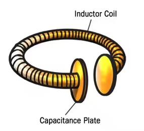
Figure 4
Based on the above theory, a coil can send electricity to several receiving devices, provided that they are all at the same resonant frequency. The researchers named this method Non-Radiative Energy Transfer because constant fields are created around the coils. This research group showed that this system could turn on or charge all the devices in the room. Of course, if the distance is long or the dimensions of the environment are large, changes must be made in the above architectural structure to be usable.
Wireless transmission of electricity over long distances
It doesn’t matter if you use an inductive or resonant-type wireless charger to supply energy to electrical equipment. In general, these two methods do not perform well over long distances because they do not have the necessary power to transmit electricity over several kilometers or from ground to space.
In the 1980s, the Canadian Communications Research Center designed a small plane to shoot energy beams from Earth. To be more precise, the drone named SHARP
It was called the Stationary High Altitude Relay Platform; it had the role of a relay. Instead of flying from one point to another, Sharp’s small plane could fly in circles with a diameter of two kilometers and an altitude of about 21 kilometers. The interesting part of the story was that the aircraft could continue to fly for several months (Figure 5).

Figure 5
The secret of Sharp’s long-duration flight was that a large transmitter on the ground sent out microwaves. The circular flight path of this plane kept it within the range of this transmitter. On the other hand, a large disc-shaped rectifier antenna was designed just behind the plane’s wings, which converted the microwave energy from the transmitter into direct current.
For this reason, the interaction of microwave waves with the rectifier antenna allowed it to play the role of a constant power source and provide energy to the Sharp aircraft as long as it was within the transmitter’s range. Rectifier antennas play an essential role in most power transmission methods. These antennas have arrays of positive and negative dipole antennas and are connected to semiconductor diodes.
In general, these antennas work based on the following architecture:
- Microwaves, part of the electromagnetic spectrum, reach the dipole antenna.
- An antenna that collects microwave energy and transmits it to diodes.
- Diodes act like switches, open or closed, allowing electrons to flow in only one direction. They direct the electrons to the rectifier antenna circuit.
- Circuits then send electrons to the parts and systems that need them.
Most of the longer-range power transmission ideas are based on rectifier antennas. David Criswell of the University of Houston has proposed using microwaves to transmit electricity from solar power plants that can be deployed on the Moon to Earth. In such a way, tens of thousands of receivers on the ground absorb this energy, and rectifier antennas convert it into electricity (Figure 6).
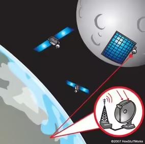
Figure 6
Microwaves can easily pass through the atmosphere, and antennas can effectively convert microwaves into electricity. Also, ground rectifier antennas can be built into a lattice framework to minimize environmental impact.
Along with all the advantages that these ideas have, they also have disadvantages, the most important of which are the following:
- Solar power stations on the Moon require monitoring, care, and maintenance. In other words, this project requires stable stations on the Moon where human forces are employed.
- Only a certain part of the Earth has a direct line of sight to the Moon at any given time. Hence, a network of satellites is needed to channel the microwaves.
- Many oppose being permanently exposed to microwaves sent to Earth from space, even if the risks are relatively small.
Although scientists have built prototypes of aircraft that run on wireless power, many larger-scale applications, such as building power stations on the Moon, remain a theory. Due to the current increase in the planet’s population, the need for enough electricity to produce and transmit it to different places is a difficult task. For this reason, wireless transmission is not just an interesting and attractive idea but a necessity.