


What is Ion-propelled aircraft?
An ion propulsion aircraft is an aircraft that uses electrohydrodynamics (EHD) to lift or propel air without the need for combustion or moving parts.
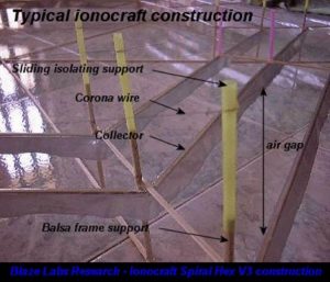
Image: Making a typical ion plane
Current designs for this type of aircraft do not provide sufficient thrust for human-crewed flight or payloads.
The principle of ion wind drift with charged particles produced by the crown was discovered shortly after discovering electricity references in 1709 in a book entitled Physical and Mechanical Experiments on Various Subjects by Francis Hawksby.
VTOL “lift” tests
American experimenter Thomas Townsend Brown spent most of his life working on this principle, mistakenly assuming that it was an anti-gravitational effect, which he called the Beefeld-Brown effect. Because his machines generated thrust in the direction of the field’s gradient, regardless of the direction of gravity, and did not operate in a vacuum, other workers realized that this effect was due to EHD.
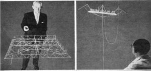
VTOL ion aircraft are sometimes called “lifts.” The prototypes could lift about one gram of weight per watt, which was not enough to lift the high-voltage power supply, which remained on the ground and supplied the aircraft with long, thin, flexible wires.
The use of EHD propulsion for lifts was studied by American aircraft designer Major Alexander Prokofieff de Seversky in the 1950s and 1960s. In 1959 he filed a patent for songcraft. He built and flew a model of the VTOL ion aircraft, which was able to maneuver laterally by changing the voltages applied in different areas. However, the heavy power supply remained external.
The 2008 Wingless Electromagnetic Air Vehicle (WEAV), a saucer-shaped EHD elevator with electrodes embedded across its surface, was developed by a team of researchers led by Subrata Roy at the University of Florida in the early 21st century. Was studied. The propulsion system uses many innovations, including magnetic fields, to increase ionization efficiency. A model with an external source achieved the minimum required to rise and float.
Self-sufficiency
21st-century power supplies are lighter and more efficient. The first ion propulsion aircraft to take off and fly using its internal power supply was a VTOL aircraft developed by Etron Krauss of Electron Air in 2006. His patent application was filed in 2014, and in 2017, he was awarded a micro-grant by Stardust Startups to support his project. The aircraft provided enough thrust to take off quickly or fly horizontally for a few minutes.
In November 2018, the first self-propelled fixed ion wing aircraft, the MIT EAD Airframe Version 2, flew 60 meters. The aircraft was developed by a team of students led by Steven Barrett of the Massachusetts Institute of Technology. Its wingspan was 5 meters, and its weight was 2.45 kg. The aircraft was launched with a catapult using an elastic band, and the EAD system kept the aircraft in low-level flight.
Principles of operation
Ionic air propulsion is a technique for creating an airflow through electrical energy without the use of any moving parts. For this reason, it is sometimes described as a “solid-state” drift. This is based on the principles of electrohydrodynamics.
Its original form consists of two parallel conductive electrodes, a leading emitter wire, and a downstream collector. When such an arrangement is fed at a high voltage (in the range of kilovolts per millimeter), the emitter ionizes the molecules in the air, which accelerate backward towards the collector and, in response, produce a propulsive force. Along the way, these ions collide with electrically neutral air molecules, accelerating them.
This effect is not directly related to electrical polarity, as ions may be positively or negatively charged. Reversing the polarity of the electrodes does not change the direction of motion because it also reverses the polarity of the charged ions. Drift is produced in one direction in each direction. For a positive corona, nitrogen ions are formed first, while oxygen ions are the primary ions for negative polarity. These ions immediately absorb various air molecules to form molecular clusters of ions of both signals that act as charge carriers.
Current EHD drives are much more efficient than conventional motors.
Unlike pure ion propulsion rockets, the principles of electrohydrodynamics do not apply in a vacuum.
Electrohydrodynamics
The thrust generated by the EHD is an example of the Biefeld-Brown effect and can be obtained through a modified use of the Child-Langmuir equation. A generalized one-dimensional approach gives the equation: F = Id / k, where
- F is the resulting force.
- I am an electric current.
- D is the air gap.
- K ion mobility is a working fluid measured in the A s2 unit system in terms of A s2 kg − 1 but is usually described in m2 V − 1 s − 1. A typical value for air at surface pressure and temperature is 1.5 × 10⁻⁴ m2 V − 1 s − 1.
This principle is also known as electro-aerodynamics (EAD) because it applies to gases such as air.
The high voltage crown wire, usually between 20 and 50 kV, is charged when the craft is turned on. When the corona wire reaches approximately 30 kV, it causes the adjacent air molecules to ionize as the electrons separate from them. As this happens, the ions are expelled from the anode and absorbed towards the collector, causing most of the ions to accelerate toward the collector. These ions move at a constant average speed, called the drift speed. Such a velocity depends on the average free path between collisions, the strength of the external electric field, and the mass of ions and neutral air molecules.
Aircraft configuration
Like a typical reaction drift, the EAD drift may be driven horizontally to power a fixed-wing aircraft or vertically to support a power-lift aircraft, sometimes referred to as a “lift.”
Plan
The components of a thrust generator An ionic thrust system consists of three parts. An emitter crown or wire, an air gap, and a collector wire or strip downstream of the emitter. A lightweight insulation frame supports the layout. To reach the saturation crown flow conditions that create the maximum thrust, the emitter and collector should be as close to each other as possible, i.e., at a distance of about a narrow air gap. However, if the emitter is too close to the collector, it tends to arch across the gap. Ion propulsion systems require a lot of precautions due to the high voltage required.
emitter
The wire emitter is usually connected to the positive terminal of the high voltage power supply. It is generally made of a small gauge bare conductor wire. While copper wire can be used, copper does not work as well as stainless steel. Similarly, thinner wires, such as gauge 44 or 50, usually work better than more common and larger sizes, such as gauge 30, because a stronger electric field around a smaller diameter wire leads to better ionization and larger corona current.
The emitter is sometimes referred to as the “crown wire” because it emits the glow of a purple crown discharge during use.
Air gap
The air gap insulates the two electrodes and allows the ions produced in the emitter to accelerate and transfer the momentum to the neutral air molecules before losing their charge in the collector. The width of the air gap is usually 1 mm / kV.
Collector
The collector creates a smooth potential surface beneath the crown wire. Types include wire mesh, parallel conducting tubes, or foil skirts with smooth, rounded edges. Sharp edges on the skirt reduce performance because it produces ions with opposite polarity to those in the thrust mechanism.
Electrohydrodynamic extruders
EHD stands for Electro Hydro Dynamics, which is the study of fluid flow under the influence of an electric field. The principle of ionic air thrust with charged particles produced from the crown has been known since the earliest days of the discovery of electricity.
One of the first references to the measurement of moving air near a pregnant tube appeared in 1709 in a book entitled “Physical and Mechanical Experiments on Various Subjects” by F. Hauksbee. Many other pioneers of electricity, including Newton, Faraday, and Maxwell, studied the phenomenon. Unfortunately, EHD is not a common theme in most high school curricula, so most people are confused when they see such devices in practice.
Electrohydrodynamic extruder effect
The EHD extruder is an electrohydrodynamic device that ionizes the air and moves the charged ion cloud in a direction that transmits momentum to neutral air molecules. We found that according to Newton’s third law of motion, action is equal to and opposite to reaction and that the EHD propeller moves in the opposite direction of the ion cloud. Ionocrafts, or ion aircraft, was the name given to the first type of vertical take-off EHD propulsors, designed in the early 1960s and part of the EHD propulsion family.
This work has become popular under the unsuitable title “Balaguer,” which relates to a kind of anti-gravity effect since more people are unaware of EHD.
It is a known fact that these devices generate thrust along their axis, not against the force of gravity expected from a gravity anti-gravity device. An EHD drive in its simplest form consists of two electrodes, one with a sharp edge, an ionizer, and the other with a flat edge, a collector, which, when fed at a high dc voltage (several kilovolts), counteracts the thrust force. The environment usually creates air.
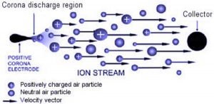
Figure: Electrohydrodynamic diagram of drift
The diagram below shows an EHDT in its most rudimentary form. It consists of a fine wire hung over a sheet of aluminum foil by lightweight insulating support such as balsa wood. If the DC high voltage source is connected, a thrust is generated that moves the device in the positive wire direction. This drift is due to the movement of air or any other dielectric fluid (insulation) around the device, which is described below.
The sharp top electrode ionizes the air. The free electrons in its vicinity accelerate toward it if the electrode is positive, separating the other electrons from the air molecules around the sharp wire.
Thus, a cloud comprises heavy positive charges, and avalanches of electrons approaching the sharp electrode cause coronary current and ionization. In their insane attack from the ion emitter to the smooth negative electrode, the positive ions collide with neutral air molecules – air particles without charge.
The force exerted on them by the electric field is compensated by the frictional force caused by the ions colliding with the neutral air molecules. As a result, the ions move through the air gap at an almost constant velocity Vd, which is proportional to the electric field given by Vd = kE, where the proportionality constant k is called the ion mobility; the higher the value, the greater the mobility (Or more speed) and less friction is provided.
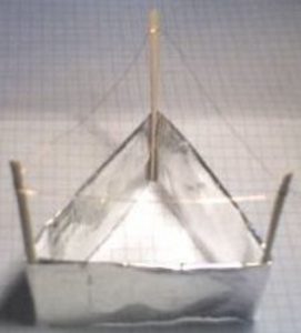
Image: Photo of electrohydrodynamic lift
The massive impact in these collisions throws a mass of neutral air down with ions.
The distance traveled in centimeters by an ionized air molecule to collide with a neutral air molecule is given by the mean free path and is equal to 5 x 10⁻³ / P where P = 760 Torr is at sea level. . The larger the air gap than the average free path, which is 6.6 x 10⁻⁶ cm, the more likely it is that the ion will repeatedly hit the neutral molecules. Therefore we will receive more effective shocks and consequent thrust. In these collisions, the ionic charge is not transmitted to the neutrals.
When they reach the lower smooth electrode, the ions, which are still positive, collide with it and neutralize themselves. But the network has no attraction for the neutral air particles that have collided along. So air flows right along the sides of the lower electrode, creating a stream of neutral air beneath the EHD device.
The fact that most ions are neutralized in the collector explains why the reading we receive from setting ion meter meters under such devices does not calculate the measured drift. In fact, for a good EHD driver, such a rate should be close to zero. However, if the force exerted by the exhaust air from the collector on a flat surface is accurately measured, we find that this force is equal to and opposite to the thrust force of the device.
Conclusion
While extensive research was conducted in the 1950s and 1960s on the use of electric propulsion for interplanetary spaceflight, many promising concepts had to be discarded due to the technological limitations of the air conditioning systems used at the time.
It is also understandable that NASA’s research and development of ion propulsion were primarily for interplanetary spaceflight in those days. The fact that crafts need a fluid environment to work has made these extraordinary devices largely out of society.