


Understand The Differences Between Zen 3 And Zen 2 Architectures In Support Of Ring Bus And Full Interconnectivity Topologies
One Of The Features That Imedi’s Company Has Long Outperformed Its Rival, Intel, In The Field Of CPU Design And Development Is Counting The Number Of Chip Cores.
Although in the past Intel processors had more power and potential in the performance and computing power of single-core processors than their red-core counterparts, when it comes to multi-core processors, this is the time to crown the kingdom.
Although the company has maintained its position in this field with strength and authority to date, if there is no change in the architectural design of its processors in the future, the page will turn and face a wall in the field of increasing the number of physical cores. Let’s wash!
As we know from the information and details published so far about the design of the architectures used by the company, the CCD structure is derived from the abbreviated term Compute Complex Die. It constitutes the physical, structural blocks of all processors based on Zen 3 architecture in the field of client category systems.
It is consumer and enterprise, but it seems that this structure suffers from the problem of limitation in increasing the number of physical cores due to how the components and indoor units require extensive and high bandwidth, which will appear sooner or later in the future.
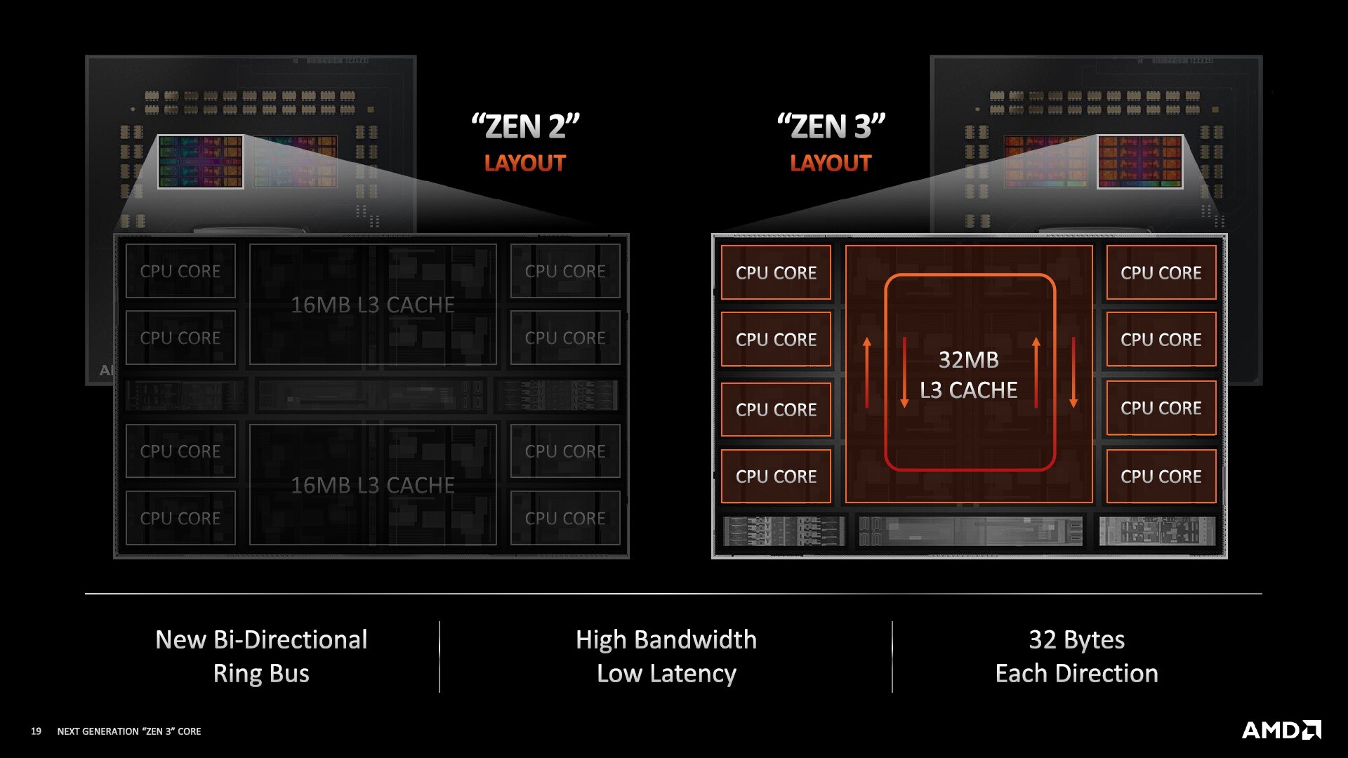
Further searching for information based on the switching of CCD structures published by AMD’s Company, we see the presence of a ring bus topology or, in other words, a ring bus in this architecture.
Imagine a bus traveling between a city’s intersections, picking up and unloading its passengers between four different buildings to understand this better.
In this example, the hypothetical bus represents the data moving between different processor computing and processing units. The buildings play the role of components such as physical cores, connections, etc., and the ring stops (Ring Stops) also play the role of bus stations…
In this case, the chip designers find the freedom to deactivate components and units, such as physical cores, by shutting down bus stops, making them inaccessible in segmenting product stacks and differentiating between them, thereby rendering the relevant computing and processing units inaccessible.
According to the example, a two-way ring bus (Ring Bus) sees the movement of two sets of data, or in other words, the bus between the intersections of the city and the predetermined route.
Although the Ring Bus topology is very complex and unique, it, unfortunately, suffers from a significant problem: the scale limitation, which is mainly due to the increase in CPU processing speed due to the rise in the number of bus stops per open CCD.
In turn, it potentially deters manufacturers from increasing the number of processor cores.
This problem is the main reason for the exit of the coaxial ring topology ( Although the Ring Bus topology is very complex and unique, it, unfortunately, suffers from a significant problem, and that is the scale limitation, which is mainly due to the increase in CPU processing speed due to the rise in the number of bus stops per open CCD. in turn, potentially deters manufacturers from increasing the number of processor cores.
This problem is the main reason for the exit of the coaxial ring topology ( Although the Ring Bus topology is very complex and unique, it, unfortunately, suffers from a significant problem, and that is the scale limitation, which is mainly due to the increase in CPU processing speed due to the rise in the number of bus stops per open CCD.
In turn, it potentially deters manufacturers from increasing the number of processor cores. This problem is the main reason for the exit of the coaxial ring topology (Coaxial Ring Topology ) in networking and data transmission.
In early 2010, Intel realized the impossibility of increasing the number of physical cores of its chips and scaling them and therefore sought to innovate through the mesh topology. The mesh topology is a more advanced ring bus with additional connection points between components and processing and computing units. It is placed as an intermediate structure between ring bus topologies and full interconnectivity.
In this type of communication, each unit is in direct contact with other departments, which is an impractical solution to improve the scale of CPUs).
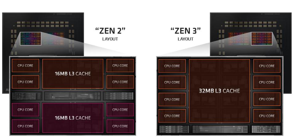
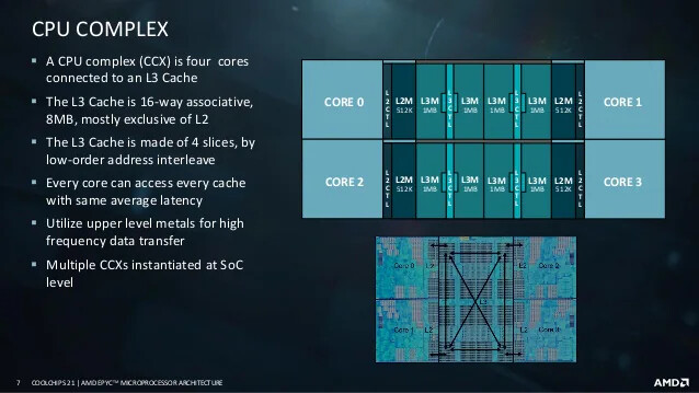
Interestingly, Imedi has not used the Ring Bus topology in the CCD structure in all the different generations of its architectures. The previous generation of Zen architecture, Zen 2, which supported the four-core CCX (abbreviated CPU Complex) structure, was a complete interconnection topology between the four computing and processing units, which are physical cores and a third-level shared cache.
I may have enjoyed it. Suppose we refer to the slide below and the part where the company had the same delay accessing each core to all third-level cache components. We can also see this feature because it can provide the same delay among all substances using topology.
The bass ring is challenging and almost impossible due to the predetermined movement of data. In cross-structure topology, each kernel has direct access to the cache simultaneously and independently of the other units in its path, so They can also send and receive their commands alone.
To understand more, consider the example of the bus again.
In the bus ring topology, the hypothetical bus must take a default route and travel from station one to two, then three, four, and so on. In this case, the passenger who gets on the bus at station number one and intends to get off at station number five must wait for four stops until arrival, but if there is one bus for each of the four lanes, the passenger can go directly to the station.
Ride number one and then get off at station number five, without having to waste time stopping the bus at each station, which in itself represents the topology of interconnection (assuming station number one as a core, station number five is a Third cache level and passenger data being transferred).
As mentioned earlier, the cross-linking topology was eventually abandoned by Imedi due to a weakness in scale, and the lot is changing to the ring-topology in Zen 3 architecture.
Finally, as a conclusion, it should be noted that the topography of the ring bus, or in other words, the ring bus, also suffered from weak sales. According to AnandTech, the media should use different alternative topologies to increase the number of processor cores.
And turn superior. The CCD structures of the company’s future chips can consist of three distinct parts stacked or layered on top of each other.
In this case, the top layer can host different levels of cache, the middle layer of physical cores, and finally, the bottom layer of internal mesh connections.