


How To Manage The Process Of Routing And Assigning IP Addresses To Routers?
All Computer Networks Need Routing Algorithms To Be Usable Efficiently. Without Algorithms, Packets Are Lost In The Network And Sent To Unrelated Clients, And In Total No Network Will Be Able To Meet The Needs Of Businesses.
Routers, the performance of the networks and protocols used in this field is not the same. For example, small networks have handheld tables, while large networks have complex correlations, and this correlation changes over short periods of time.
The same structure of routing tables is not fixed in large networks. Dynamic routing was invented to solve these problems and implement a mechanism that can create automated table structures.
Manage The Process Of Routing And Assigning IP Addresses To Routers?
Dynamic routing tries to keep networks as stable as possible and away from common problems, which is why it is widely used on the Internet.
What is static routing?
Static Routing refers to the manual management of routes. To be more precise, the network administrator manually adds routes to the routing table. Static routing is a good option for small networks because if the network changes, the routing addresses do not change and therefore work well on small networks. Still, as the network grows, manual route management becomes difficult, and the network administrator is forced to automate management.
URLs use dynamic routing techniques. The problem with static routing is that the router spends processing power calculating, analyzing, and updating the routing process.
If necessary, network administrators can supplement dynamic paths with static paths or distribute static paths within dynamic routing algorithms. Still, they cannot distribute routing information computed by dynamic routing algorithms in a static routing table.
Static routing has advantages and disadvantages, such as simple implementation, greater security in routing, lack of sharing information with other routers, and the lack of additional slag that consumes system resources too much.
One of the most important advantages of static routing is improved security because the routes are defined manually, and the network administrator has close supervision.
However, static routing also has its drawbacks.
Suitable for small networks, traffic cannot redirect if a link breaks, and any changes made to the router that affect the network must be manually managed.
One of the most important advantages of static routing is improved security because the routes are defined manually, and the network administrator has close supervision. However, static routing also has its drawbacks.
Suitable for small networks, traffic cannot redirect if a link breaks, and any changes made to the router that affect the network must be manually managed.
One of the most important advantages of static routing is improved security because the routes are defined manually, and the network administrator has close supervision.
However, static routing also has its drawbacks. Suitable for small networks, traffic cannot redirect if a link breaks, and any changes made to the router that affect the network must be manually managed.
How does static routing work?
To be able to show the static routing process, we need Packet Tracer emulator software. Figure 1 shows how routers are defined in this software. The topology used in this tutorial is as shown in Figure 2.
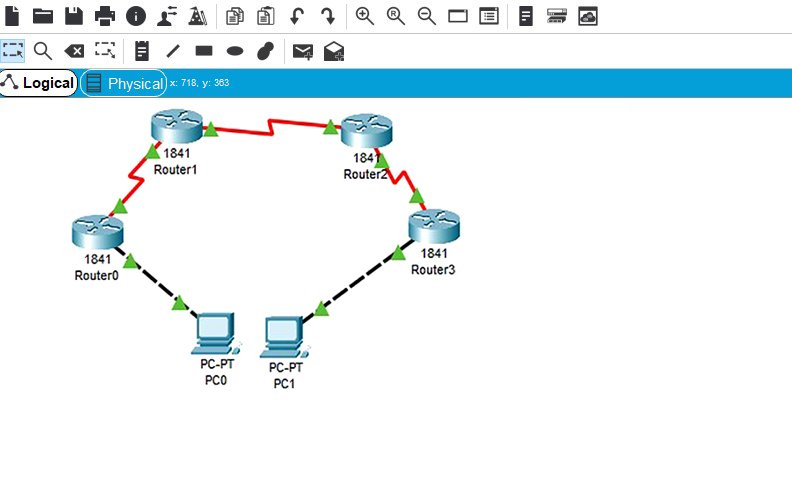
figure 1
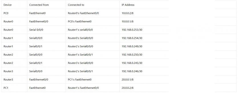
figure 2
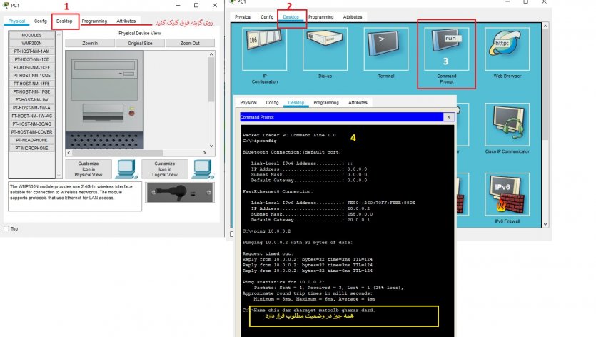
In the first step, we need to assign the IP address to the PC0 computer, equal to 10.0.0.2/8 (Figure 3). Would you please do the same with PC1 and assign it an IP address of 20.0.02 / 8?
Assign an IP address to the router interface
Next, we need to assign the IP address to the router interface. To do this, double-click on the Router0 component, then click on CLI and press the Enter key at the bottom of the right panel window to access the Router0 command line (Figure 4).
Two fastEthernet0 / 0 and Serial0 / 0.0 interfaces belonging to Router0 are used in this topology. By default, connections on routers are managed and ready to use. We need to configure the IP address and other related parameters before actually using them in routing. Interface mode is used to assign IP addresses and other parameters. Interface status can be used by global configuration mode. The following commands are used to access the global configuration status:
Router> enable
Router # configure terminal
Enter configuration commands, one per line. End with CNTL / Z.
Router (config) #
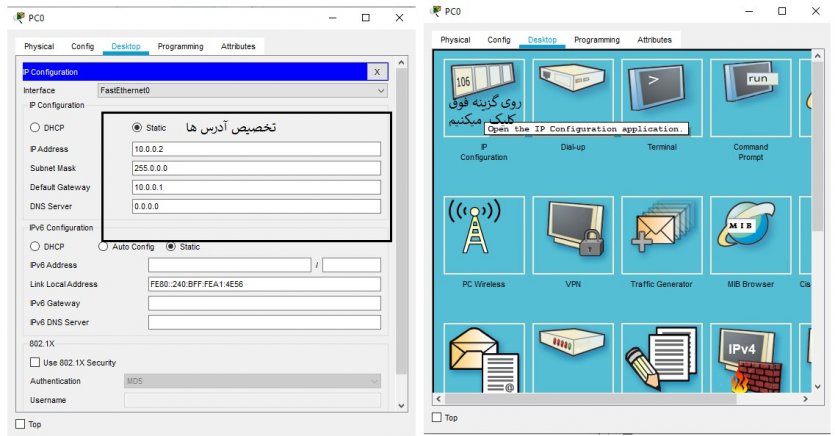
Figure 3
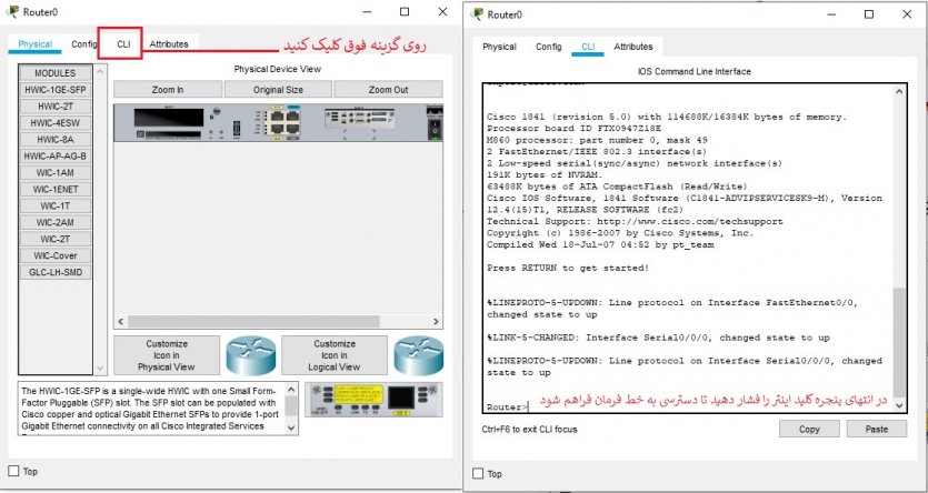
Figure 4
Network administrators can use the global configuration mode to enter the interface configuration mode. We are now ready to configure the interface according to work requirements. The following commands assign an IP address to FastThernet0.0.
Router (config) #interface fastEthernet 0/0
Router (config-if) #ip address 10.0.0.1 255.0.0.0
Router (config-if) #no shutdown
Router (config-if) #exit
Router (config) #
- Interface FastEthernet 0/0: This command is used to enter the interface configuration mode.
- Ip address 10.0.0.1 255.0.0.0: This program assigns an IP address to the interface.
- No shutdown: This allows the interface to continue working after configuration.
- Exit: This command is used to return to the global configuration state.
The serial interface requires two parameters, clock rate and bandwidth. Each interface cable has two parameters, DTE and DCE. We can use the show controllers interface command in the licensing mode to check the status of the end cable. Note the commands used in this field:
Router # show controllers serial 0/0/0
Interface Serial0 / 0/0
Hardware is PowerQUICC MPC860
DCE V.35, clock rate 2000000
[Output omitted]
The fourth line confirms that the DCE is connected to the serial cable. If you see DTE instead of DCE in this section, skip these parameters. We have now obtained the required information, and we have to assign the IP address to the serial interface. For this purpose, we execute the following commands:
Router # configure terminal
Enter configuration commands, one per line. End with CNTL / Z.
Router (config) #interface serial 0/0/0
Router (config-if) #ip address 192.168.0.253 255.255.255.252
Router (config-if) #clock rate 64000
Router (config-if) #bandwidth 64
Router (config-if) #no shutdown
Router (config-if) #exit
Router (config) #
Router # configure terminal: This command is used to enter the global configuration mode.
Router (config) #interface serial 0/0/0: This command is used to enter the interface configuration state.
Router (config-if) #ip address 192.168.0.253 255.255.255.252:
This command assigns an IP address to the interface. For the serial link, we use the IP address of the subnet / 30.
Router (config-if) #clock rate 64000 and Router (config-if) #bandwidth 64:
In the real world, these parameters control the data flow between serial links and must be set by the service provider. In the laboratory, you do not need to worry about the values of these parameters.
- Router (config-if) #no shutdown: This command allows the interface to work smoothly.
- Router (config-if) #exit: This command is used to return to the global configuration state.
We use the same commands to assign IP addresses to other interfaces on other routers. Note that we set the clock rate and bandwidth parameters only on the DCE serial interface. The following commands assign an IP address to the Router1 interface (Figure 5).
Router> enable
Router # configure terminal
Enter configuration commands, one per line. End with CNTL / Z.
Router (config) #interface serial 0/0/0
Router (config-if) #ip address 192.168.0.254 255.255.255.252
Router (config-if) #no shutdown
Router (config-if) #exit
Router (config) #interface serial 0/0/1
Router (config-if) #ip address 192.168.0.249 255.255.255.252
Router (config-if) #clock rate 64000
Router (config-if) #bandwidth 64
Router (config-if) #no shutdown
Router (config-if) #exit
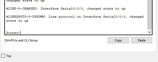
Figure 5
We now know how to assign IP addresses to links. Repeat the same to assign the IP address to the connections on Router2.
Router> enable
Router # configure terminal
Enter configuration commands, one per line. End with CNTL / Z.
Router (config) #interface serial 0/0/0
Router (config-if) #ip address 192.168.0.250 255.255.255.252
Router (config-if) #no shutdown
Router (config-if) #exit
Router (config) #interface serial 0/0/1
Router (config-if) #ip address 192.168.0.245 255.255.255.252
Router (config-if) #clock rate 64000
Router (config-if) #bandwidth 64
Router (config-if) #no shutdown
Router (config-if) #exit
The commands used in connection with Router3 are the same as before.
Router> enable
Router # configure terminal
Enter configuration commands, one per line. End with CNTL / Z.
Router (config) #interface fastEthernet 0/0
Router (config-if) #ip address 20.0.0.1 255.0.0.0
Router (config-if) #no shutdown
Router (config-if) #exit
Router (config) #interface serial 0/0/0
Router (config-if) #ip address 192.168.0.246 255.255.255.252
Router (config-if) #no shutdown
Router (config-if) #exit
We are done. Routers now have information about the networks on which they are connected. Note that routers do not exchange any network information with each other based on the default approach. For this reason, we must use a mechanism to share this information. This mechanism is known as routing.
Static routing configuration
On Cisco routers, the Ip route adds static routes to the router routing table. The above command has two syntactic combinations as follows:
ip route destination_network_ # [subnet_mask] IP_address_of_next_hop_neighbor [administrative_distance] [permanent]
Or
IP route destination_network_ # [subnet_mask] interface_to_exit [administrative_distance] [permanent]
- destination_network _ # [subnet_mask]: The first parameter of the above command used to specify the destination network address. If you are using subnets, you must specify a subnet mask.
- Subnets are a special type of small-scale network that is based on the division of a large network. Subnets are created for various reasons, such as easier management of large networks, increased communication infrastructure security level, etc. If you do not have a subnet, you must delete the subnet mask value.
- IP_address_of_next_hop_neighbor / interface_to_exit: The above parameter is a solution to reach the destination network. The above commands use separate methods for assigning values. The first parameter prepares the IP address of the adjacent hop. It notifies the router that if it has packets belonging to the destination network, it will forward the packet to the IP address of the adjacent hop.
The second command does the same thing differently, except it specifies the exit interface instead of the next IP hop address. In other words, the above command notifies the router if it removes the packet belonging to the destination whose parameters have already been specified from its interface. The device connected to the end router receives this closed interface and prevents it from being lost.
Administrative_distance
administrative_distance Allows routers to find the best path between two or more networks that use different routing protocols to reach a specific destination. In other words, they choose a safe path. In this case, the path with the lowest AD value is selected when sending packets. By default, the static path has two AD values, depending on the previous parameter. If you have the address of an adjacent IP hop address, the default value of AD is one.
If you are using the exit interface, the default value of AD is 0. This parameter allows us to create multiple static routes for a destination. For example, we can create the main and backup path for the destination network. To create a backup path, we need to set the AD value above the default value and set it to 2 or 3, for example.
Permanent
When a route is lost, the router removes it from the routing table. The Permanent parameter allows information to be stored in the routing table even if a path is lost. The above parameter is optional, and you do not need to use it. If you do not use it, the router will remove the lost path from the routing table. Some people use this parameter for security reasons and are reluctant to transfer packets the other way.
Now that you know the Ip route command and its parameters let’s test how to implement it on your network.
Static path configuration
By default, when a packet enters the interface, the router checks the destination registered in the packet and compares it with the routing table. If it matches, it transmits the packet from the interface. If no match is found in the routing table, it will delete that packet. This is the default behaviour of the router. We do not need to configure connected networks directly here.
Run the following command in the router configuration mode.
Router0
Router (config) #ip route 20.0.0.0 255.0.0.0 192.168.0.254
The above command tells the router to deliver the packet to 192.168.0.254 whenever it receives a packet for the network 20.0.0.0. Network 10.0.0.0 is connected directly, so we do not need to configure it here.
Router1
Router (config) #ip route 10.0.0.0 255.0.0.0 192.168.0.253
Router (config) #ip route 20.0.0.0 255.0.0.0 192.168.0.250
On this router both networks are accessible through other routers, so we need to configure the route for both 10.0.0.0 and 20.0.0.0 networks.
Router 2
Router (config) #ip route 10.0.0.0 255.0.0.0 192.168.0.249
Router (config) #ip route 20.0.0.0 255.0.0.0 192.168.0.246
Similar to Router 1, we need to configure the route for both networks on this router twice.
Router 3
Router (config) #ip route 10.0.0.0 255.0.0.0 192.168.0.245
Network 20.0.0.0 is connected directly, so all we have to do is configure Network 10.0.0.0 on this router.
That’s all we do for packet switching from one network to another. We use the ping command to make sure everything is done correctly. Run the PC1 command line and run the ping command to check the connection status of PC0 (Figure 6)